Figure 37: configuration jumper (jp6) location, Figure 38: configuration jumper (jp7) location – Epson S1D13705 User Manual
Page 326
Page 14
Epson Research and Development
Vancouver Design Center
S1D13705
S5U13705B00C Rev. 2.0 Evaluation Board User Manual
X27A-G-014-02
Issue Date: 2002/09/16
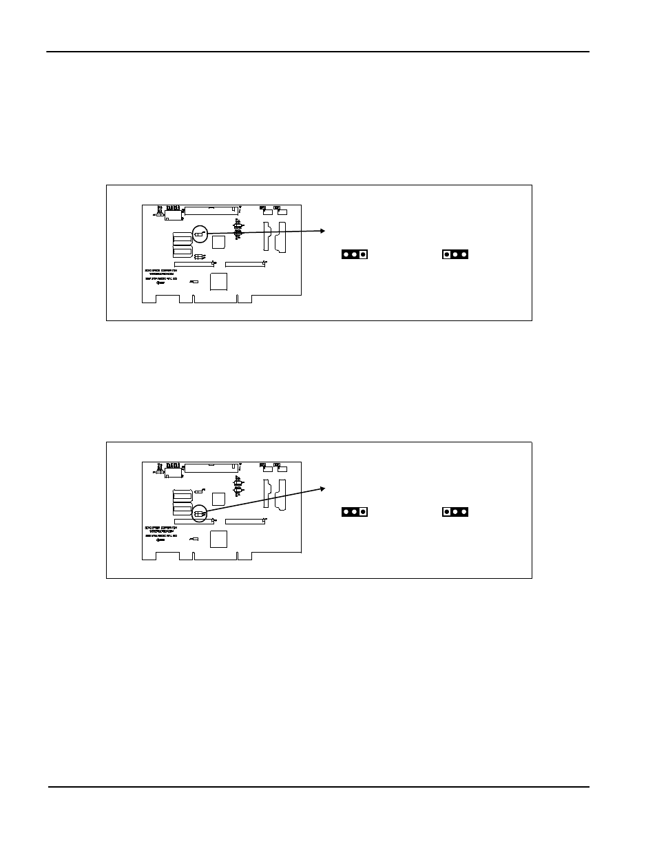
JP6 - LCDPWR Polarity
LCDPWR output from S1D13705 is only active high but some panels may require an active
low signal. To provide both active high and active low signals, the output from S1D13705
is inverted and the selection is made by the setting of JP6
When the jumper is in position 1-2, LCDPWR signal to the panel is active low
When the jumper is in position 2-3, LCDPWR signal to the panel is active high
Figure 3-7: Configuration Jumper (JP6) Location
JP7 - CLKI Selection
JP7 selects the source for CLKI input on S1D13705.
When the jumper is in position 1-2, CLKI signal is provided by external oscillator U2
When the jumper is in position 2-3, CLKI signal is the same as BCLK signal
Figure 3-8: Configuration Jumper (JP7) Location
JP6
LCDPWR
LCDPWR
Active High
Active Low
JP7
CLKI
External
Oscillator (U2)
Same as
BCLK