2 s1d13705 hardware configuration, Table 42: summary of power-on/reset options, Table 43: host bus interface selection – Epson S1D13705 User Manual
Page 414
Page 28
Epson Research and Development
Vancouver Design Center
S1D13705
Interfacing to the Motorola ‘Dragonball’ Family of Microprocessors
X27A-G-007-04
Issue Date: 01/02/13
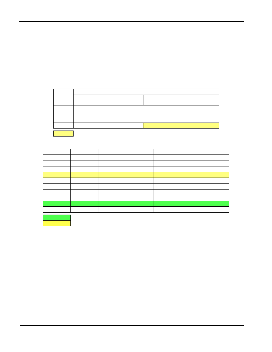
4.4.2 S1D13705 Hardware Configuration
The S1D13705 uses CNF3 through CNF0 and BS# to allow selection of the bus mode and
other configuration data on the rising edge of RESET#. Refer to the S1D13705 Hardware
Functional Specification, document number X27A-A-001-xx for details.
The tables below show those configuration settings important to the MC68K #1 and
Generic #1 host bus interfaces.
Table 4-2: Summary of Power-On/Reset Options
S1D1370
5
Pin Name
value on this pin at the rising edge of RESET# is used to configure: (1/0)
0
1
CNF0
See Table 2-3: “Host Bus Interface Selection”
CNF1
CNF2
CNF3
Little Endian
Big Endian
= configuration for MC68VZ328 support
Table 4-3: Host Bus Interface Selection
CNF2
CNF1
CNF0
BS#
Host Bus Interface
0
0
0
X
SH-4 interface
0
0
1
X
SH-3 interface
0
1
0
X
reserved
0
1
1
X
MC68K #1, 16-bit
1
0
0
X
reserved
1
0
1
X
MC68K #2, 16-bit
1
1
0
0
reserved
1
1
0
1
reserved
1
1
1
0
Generic #1, 16-bit
1
1
1
1
Generic #2, 16-bit
= configuration for MC68VZ328 using Generic #1 host bus interface
= configuration for MC68VZ328 using MC68K #1 host bus interface