5 lcd interface pin mapping, Table 51: lcd signal connector (j5), Dual – Epson S1D13705 User Manual
Page 330
Page 18
Epson Research and Development
Vancouver Design Center
S1D13705
S5U13705B00C Rev. 2.0 Evaluation Board User Manual
X27A-G-014-02
Issue Date: 2002/09/16
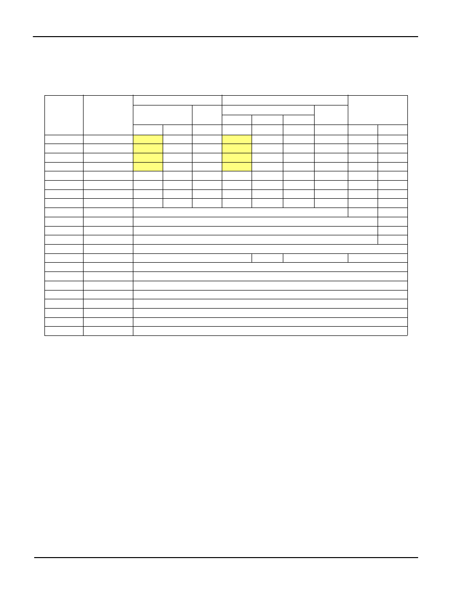
5 LCD Interface Pin Mapping
Note
1
These pin mappings use signal names commonly used for each panel type, however
signal names may differ between panel manufacturers. The values shown in brackets
represent the color components as mapped to the corresponding FPDATxx signals at
the first valid edge of FPSHIFT. For further FPDATxx to LCD interface mapping, see
S1D13705 Hardware Functional Specification, document number X27A-A-001-xx.
2
LCDPWR on J5 can be inverted by setting JP6 to 1-2.
Table 5-1: LCD Signal Connector (J5)
Pin Name
Connector Pin
No.
Monochrome Passive
Color Passive Panel
Color TFT Panel
Single
Dual
Single
Dual
Format 1 Format 2
4-bit
8-bit
8-bit
4-bit
8-bit
8-bit
8-Bit
9-bit
12-bit
BFPDAT0
1
driven 0
D0
LD0
driven 0
D0 (B5)
1
D0 (G3)
1
LD0 (lR2)
1
R2
R3
BFPDAT1
3
driven 0
D1
LD1
driven 0
D1 (R5)
1
D1 (R3)
1
LD1 (lB1)
1
R1
R2
BFPDAT2
5
driven 0
D2
LD2
driven 0
D2 (G4)
1
D2 (B2)
1
LD2 (lG1)
1
R0
R1
BFPDAT3
7
driven 0
D3
LD3
driven 0
D3 (B3)
1
D3 (G2)
1
LD3 (lR1)
1
G2
G3
BFPDAT4
9
D0
D4
UD0
D0 (R2)
1
D4 (R3)
1
D4 (R2)
1
UD0 (uR2)
1
G1
G2
BFPDAT5
11
D1
D5
UD1
D1 (B1)
1
D5 (G2)
1
D5 (B1)
1
UD1 (uB1)
1
G0
G1
BFPDAT6
13
D2
D6
UD2
D2 (G1)
1
D6 (B1)
1
D6 (G1)
1
UD2 (uG1)
1
B2
B3
BFPDAT7
15
D3
D7
UD3
D3 (R1)
1
D7 (R1)
1
D7 (R1)
1
UD3 (uR1)
1
B1
B2
BFPDAT8
17
GPIO1
B0
B1
BFPDAT9
19
GPIO2
R0
BFPDAT10
21
GPIO3
G0
BFPDAT11
23
GPIO4
B0
BFPSHIFT
33
FPSHIFT
BDRDY
35 & 38
MOD
FPSHIFT2
MOD
DRDY
BFPLINE
37
FPLINE
BFPFRAME
39
FPFRAME
GND
2-26 (Even Pins)
GND
VLCD
30
Adjustable -24V to -14V negative LCD bias
LCDVCC
32
LCDVCC (3.3V / 5.0V)
+12V
34
+12V
VDDH
36
Adjustable +23V to +40V positive LCD bias
BLCDPWR
40
LCDPWR
2
(for controlling on-board LCD bias power supply on/off)