2 installation and configuration, Table 21: configuration dip switch settings, Table 22: host bus selection – Epson S1D13705 User Manual
Page 296
Page 8
Epson Research and Development
Vancouver Design Center
S1D13705
S5U13705B00C Rev. 1.0 ISA Bus Evaluation Board User Manual
X27A-G-005-03
Issue Date: 01/02/13
2 Installation and Configuration
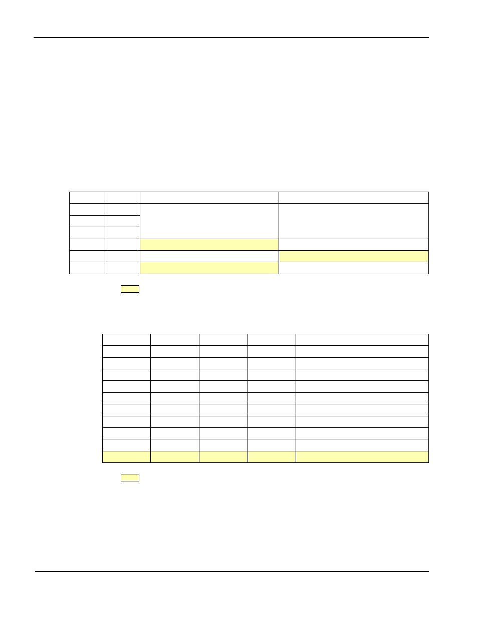
The S1D13705 has four configuration inputs, CNF[3:0], which are read on the rising edge
of RESET# and are fully configurable on this evaluation board. One six-position DIP
switch is provided on the board to configure the four configuration inputs, select the
S5U13705B00C memory/register start address, and enable/disable hardware power save
mode.
The following settings are recommended when using the S5U13705B00C with the ISA
bus.
Table 2-1: Configuration DIP Switch Settings
Switch
Signal
Closed (0 or low)
Open (1 or high)
S1-1
CNF0
See “Host Bus Selection” table below
See “Host Bus Selection” table below
S1-2
CNF1
S1-3
CNF2
S1-4
CNF3
Little Endian
Big Endian
S1-5
ADDR
Memory/Register Start Address = C0000h
Memory/Register Start Address = F00000h
S1-6
GPIO0
Hardware Suspend Disable
Hardware Suspend Enable
= recommended settings (configured for ISA bus support)
Table 2-2: Host Bus Selection
S1-3
S1-2
S1-1
BS#
Host Bus Interface
0
0
0
X
SH-4 bus interface
0
0
1
X
SH-3 bus interface
0
1
0
X
reserved
0
1
1
X
MC68K bus interface #1, 16-bit
1
0
0
X
reserved
1
0
1
X
MC68K bus interface #2, 16-bit
1
1
0
0
reserved
1
1
0
1
reserved
1
1
1
0
Generic #1, 16-bit
1
1
1
1
Generic #2, 16-bit
= recommended settings (configured for ISA bus support)