3 baseline ctog-250 deployment, 1 connecting the ctog-250 system components – Comtech EF Data CTOG-250 User Manual
Page 87
CTOG-250 Comtech Traffic Optimization Gateway
Revision 1
Quick Start Guide
MN-CTOG250
6–3
6.3
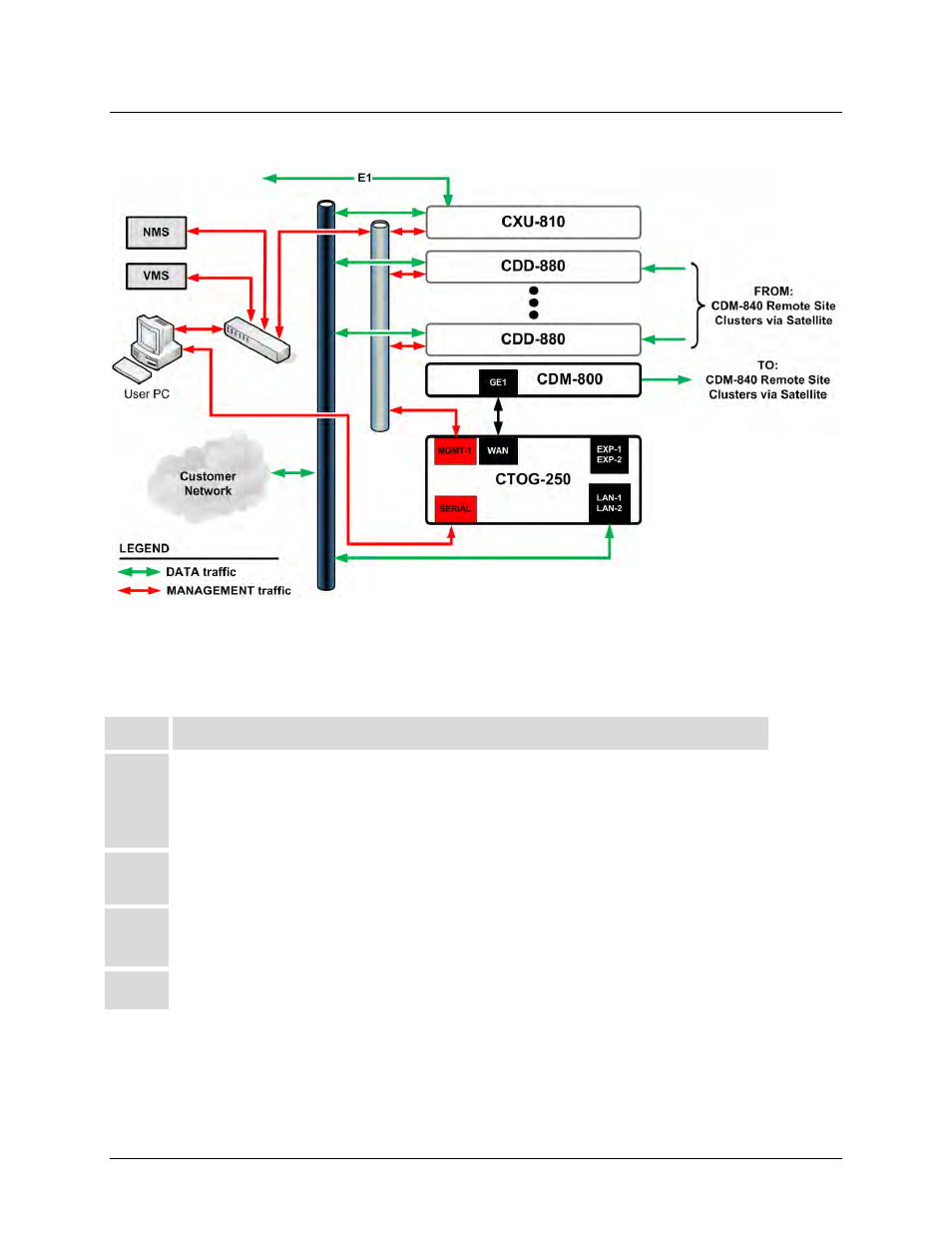
Baseline CTOG-250 Deployment
Figure 6-1. CTOG-250 Routed Implementation in an Advanced VSAT Network
6.3.1 Connecting the CTOG-250 System Components
Step
Task
1
Connect the GigE ‘MGMT-1’ Management Port on the CTOG-250 chassis back panel to the User PC
via a 10/100/1000 BaseT Ethernet Switch using CAT5 Ethernet cables.
(An RJ-45 Ethernet crossover cable can be substituted to connect the CTOG-250 directly to the User PC
without the use of a switch.)
2
Connect the CTOG-250 Console Serial Cable from the ‘SERIAL’ port on the CTOG-250 chassis back
panel and a serial COM port on the User PC.
3
Connect a CAT5 Ethernet cable from the ‘WAN’ port on the C TOG-250 chassis back panel to the
‘GE1’ port on the CDM-800 rear panel.
4
Connect the CTOG-250 and the CDM-800 to a suitable power supply and turn the units ON.