Comtech EF Data CTOG-250 User Manual
Page 101

CTOG-250 Comtech Traffic Optimization Gateway
Revision 1
Quick Start Guide
MN-CTOG250
6–17
Figure 6-4 summarizes the connections required for a basic VMS-enabled 1:1 redundant
configuration. Key features of this configuration are identified in Table 6-1:
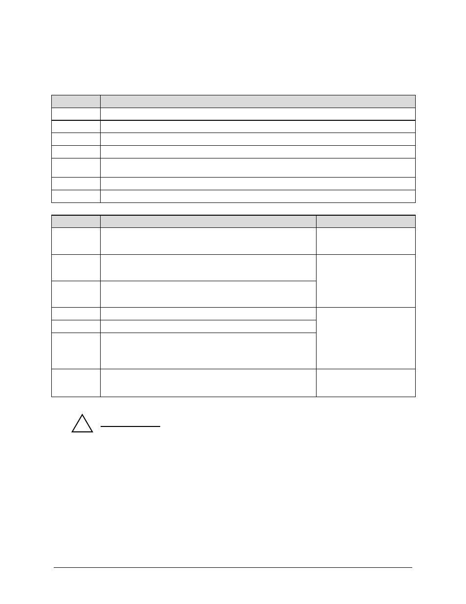
Table 6-1. Figure 6-4 1:1 Redundant Configuration Features
Figure 6-4 NOTES
1. This figure depicts use of a North American AC Power Splitter Cord (CEFD P/N PP-0020563).
For other regions, use CEFD P/N PP-0020564 or contact your local sales representative.
(Image source: Quail Electronics, Inc.)
2. See
MN/22156 Vipersat VMS v3.9.x Vipersat Management System User Guide MN/22156
Vipersat VMS v3.9.x Vipersat Management System User Guide for information on N:M
configurations.
Feature
Description
A1
Unit A – CTOG-250 Comtech Traffic Optimization Gateway
A2
Unit A – CDM-800 Gateway Router
B1
Unit B – CTOG-250 Comtech Traffic Optimization Gateway
B2
Unit B – CDM-800 Gateway Router
C
CDD-880 Multi Receiver Router (purchased separately, shown for reference only, power connection not shown
for clarity)
D
Network Controller AC Power Bus
E
User Advanced VSAT Network Management Setup, including VMS Server
Connection Description
Comments
1
AC Power Splitter Cord connection:
CTOG-250 / CDM-800 ► Network Controller AC Power Bus outlets
CEFD P/N PP-0020563
See Note 1
2
Unit A CTOG-250 to CDM-800 Ethernet connection:
CTOG-250 ‘WAN’ port ► CDM-800 ‘GE-1’ port
Operational bridge between
CTOG-250 and CDM-800. See
Figure 6-2 in Sect. 6.3.1.
3
Unit B CTOG-250 to CDM-800 Ethernet connection:
CTOG-250 ‘WAN’ port ► CDM-800 ‘GE-1’ port
4
Unit A CTOG-250 ‘MGMT-1’ port ► User PC via management network
Remote Product Management
(M&C) Ethernet connections –
all CAT5 Ethernet cables are
user-provided.
5
Unit B CTOG-250 ‘MGMT-1’ port ► User PC via management network
6
CDD-880 management Ethernet connection:
‘ETHERNET | TRAFFIC/MANAGEMENT | GE’ port ► User PC via
management network
7
Network Controller AC Power Bus management Ethernet connection:
‘Ethernet’ port ► VMS Server via management network
Server Technology horizontal
Sentry™ PowerTower XL IP
Remote AC Power Control Bus
