Comtech EF Data CTOG-250 User Manual
Page 33
CTOG-250 Comtech Traffic Optimization Gateway
Revision 1
Introduction
MN-CTOG250
1–11
1.3.3.1.3
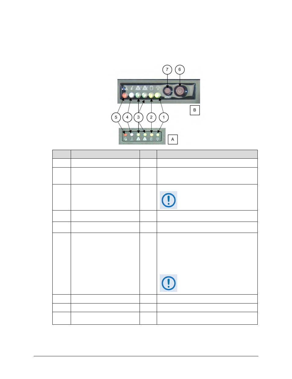
Using the Front Panel Operation Indicators and Controls
The CTOG-250 Front Bezel and chassis front panel feature six operational indicators. Control
buttons are also provided on the chassis front panel. Figure 1-9 identifies these features.
Item
Description
Color Function
A
Indicator Panel – Front Bezel
N/A
---
B
Chassis Front Panel Controls with
Light-Emitting Diode (LED)
Indicators
N/A
---
1
Power Indicator
Green
Indicates CTOG-250 power is ON when lit.
This LED should be continuously lit
during normal operation.
2
Hard Drive Access Indicator
Amber Indicates read/write activity on the installed hard
drive(s) or DVD-ROM drive (if installed) when flashing.
3
Network 1 (right) & Network 2 (left)
Activity Indicators
Green Indicates network traffic activity for the Expansion
Traffic 1 or 2 interfaces when flashing.
4
Operating Temperature Indicator
White
•
When flashing – Indicates a fan failure.
•
When continuously lit – Indicates conditions
exist for overheating. This may be due to:
o
High ambient room temperature
o
Operation without the top covers installed
o
An obstruction to the chassis internal airflow
o
Heat sink installation issues
This LED will remain flashing/lit until
the issue is resolved.
5
Power Failure Indicator
Red
Indicates a power supply failure when flashing.
6
Power Button
N/A
Use this button to power up/power down the chassis.
7
Reset Button
N/A
Use this button to perform a soft reboot of the
operating system.
Figure 1-9. CTOG-250 – Front Panel Operational Indicators and Controls