1 functional overview – Comtech EF Data CTOG-250 User Manual
Page 65
CTOG-250 Comtech Traffic Optimization Gateway
Revision 1
Back Panel Connections
MN-CTOG250
3–17
3.3
CDM-800 Gateway Router Operation and Connection Quick Reference
This manual assumes user familiarity with the CDM-800 Gateway Router. The
information presented here is intended as a quick reference – this manual does not
serve as replacement documentation for the CDM-800 user. For detailed
information on the CDM-800’s features, operations, and maintenance, see the
CDM-800 Gateway Router Installation and Operation Manual (CEFD P/N
MN-CDM800).
• Sect. 3.4 CTOG-250 / CDM-800 Basic Connection and Configuration Reference
• Chapter 6. QUICK START GUIDE
3.3.1
Functional Overview
Starting with Firmware Ver. 1.5.1.X, the CDM-800 is no longer supported in
standalone mode. The CDM-800 must be paired with a CTOG-250.
The CDM-800 unit acts as the modulator for the CTOG-250 unit. This means that, when the
CTOG-250/CDM-800 are paired as they are with this configuration, the CDM-800 unit places
itself into a bypass mode and the CTOG-250 performs the tasks of traffic shaping, optimization
and prioritization.
The CDM-800 serves in tandem as the Forward Error Correction (FEC) module, and modulates
the traffic stream from the CTOG-250 by passing that stream directly to the CDM-800
modulator. When in CTOG-250 bypass mode, all packets destined to the remote as received
directly by the CDM-800 will be dropped. User traffic must be directed through the CTOG-250
LAN ports.
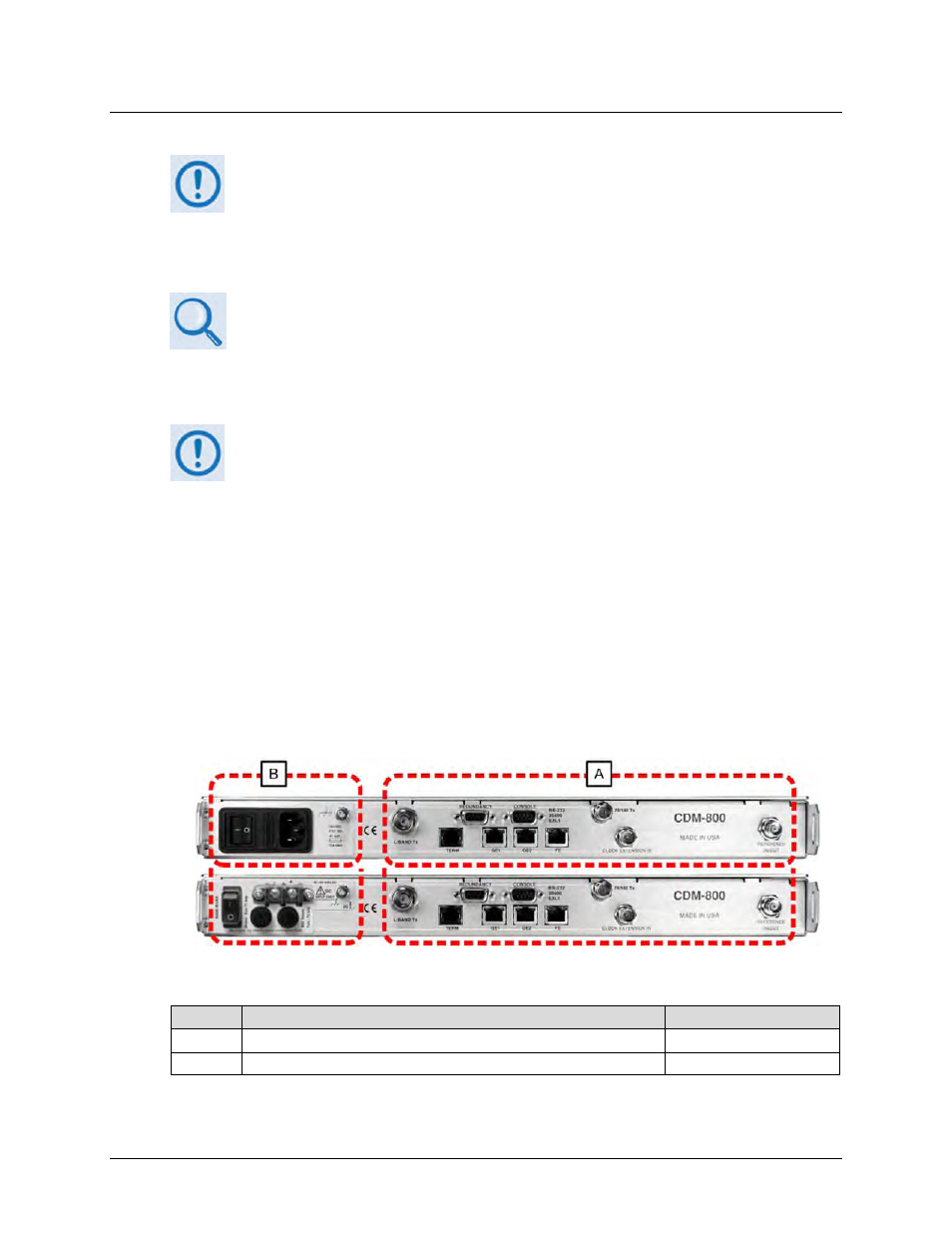
The CDM-800 Gateway Router rear panel connectors (Figure 3-12) provide all necessary
external connections between the CTOG-250 as well as other equipment.
Feature
Description
See Chapter Sect.
A
Common Operational Connections Interface
3.3.2
B
AC or DC Power and Ground Interface
3.3.3
Figure 3-12. CDM-800 Gateway Router – Rear Panel Features
(TOP) Standard AC Unit
(BOTTOM) Optional 48V DC Unit