3 cdm-800 power and ground connections – Comtech EF Data CTOG-250 User Manual
Page 67
CTOG-250 Comtech Traffic Optimization Gateway
Revision 1
Back Panel Connections
MN-CTOG250
3–19
3.3.3
CDM-800 Power and Ground Connections
PROPER GROUNDING PROTECTION IS REQUIRED. The equipment must be connected
to the protective earth connection at all times. It is therefore imperative that the unit
is properly grounded, using the ground stud provided on the unit rear panel, during
installation, configuration, and operation.
1. See CDM-800 Gateway Router Installation and Operation Manual (CEFD P/N
MN-CDM800) for detailed information about applying power to the CDM-800
and replacing its fuses.
2. Use the #10-32 stud, located adjacent to either power interface, for
connecting a common chassis ground among equipment.
3.3.3.1 CDM-800 115V/230V Alternating Current (AC) Power and Ground
Interface (Standard)
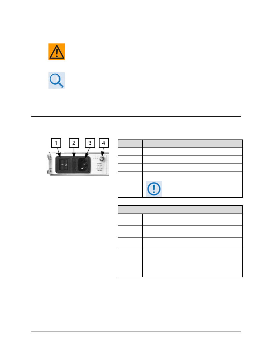
Figure 3-13. CDM-800 AC Power and Ground Interface
Feature
Description
1
On / Off Switch
2
Press-fit Fuse Holder
3
IEC Three-prong Connector
4
#10-32 Grounding Stud
The AC power interface provides
the safety ground
AC Power Specifications
Input
Power
40W maximum, 20W typical
Input
Voltage
100V to 240V AC, +6%/-10%, autosensing
(total absolute max. range is 90V to 254V AC)
Connector
Type
IEC
Fuse
Protection
•
Line and neutral fusing
•
(2X) 20mm Slow-blow type fuses (for 115V or 230V
AC operation):
o Without BUC – T2.5A (2.5A)
o With BUC – T4.5A (4.5A)