Comtech EF Data CTOG-250 User Manual
Page 229
CTOG-250 Comtech Traffic Optimization Gateway
Revision 1
Appendix E
MN-CTOG250
E–7
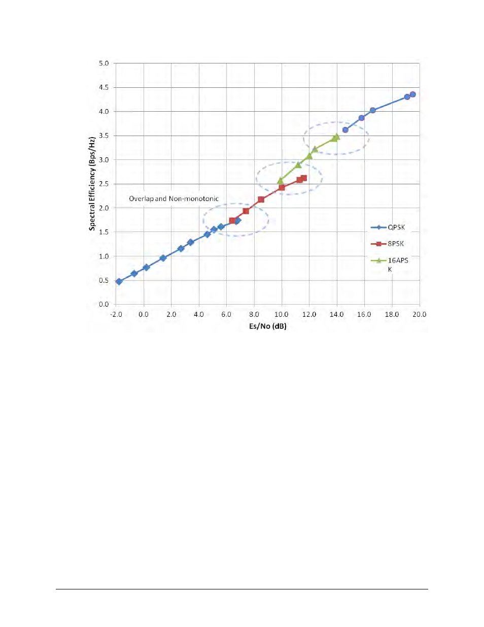
Figure E-2. Spectral Efficiency vs. Advanced VSAT Es/No @ QEF
On the previous page, Figure E-1 provides the logic diagram for packet handling and processing
by the CTOG-250.
Figure E-2 depicts considerable overlap of ModCod combinations. This overlap implies omission
of some of the ModCods; therefore, without dropping some of the ModCods, there is a non-
monotonic change of Bits/Hz with changing Es/No. As this would result in an unstable system,
re-sorting the DVB-S2 table resolves this.
Also, a practical system needs some hysteresis to provide orderly transition to adjacent
ModCods and avoid dithering. The minimum distance between adjacent ModCods must be at
least the amount of hysteresis – the figure used for hysteresis is fixed in the Advanced VSAT at
0.5 dB. The actual Es/No values used are based on the guaranteed Es/No values + Target Es/No
Margin + modulation type impairment, not the DVB-S2 ideal Es/No figures.
Taking into account the ModCod spacing, hysteresis, Target Es/No Margin, modulation type
impairment and monotonic behavior suggests a practical way to select the Es/No thresholds for
switching ModCods, and a way to prune ModCods from the list. During parameter configuration,
the modem selects the usable ModCods.