2 cdm-800 rear panel – operational connections – Comtech EF Data CTOG-250 User Manual
Page 66
CTOG-250 Comtech Traffic Optimization Gateway
Revision 1
Back Panel Connections
MN-CTOG250
3–18
3.3.2
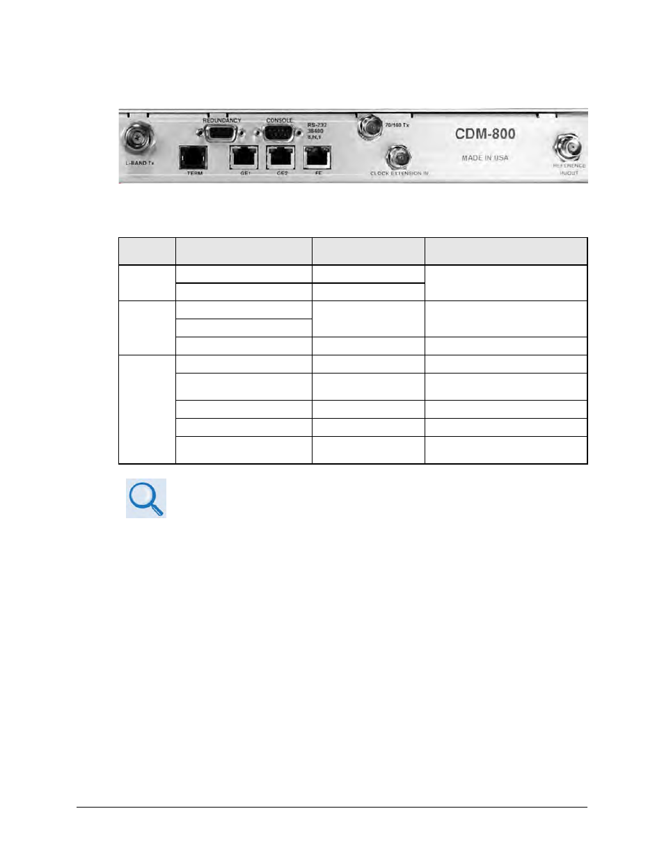
CDM-800 Rear Panel – Operational Connections
The table that follows summarizes the connectors provided here, grouped according to service
function.
Connector
Group
Connector Name
Connector Type
Connector Function
IF
L-BAND Tx
Type ’N’ female (L-Band)
IF Tx Output
70/140 Tx
BNC female (70/140 MHz)
Terrestrial
Data
GE1
RJ-45 female
10/100/1000 BaseT Gigabit Ethernet
Traffic Interface
GE2
CLOCK EXTENSION IN
BNC female
G.703 Clock Extension Input
Utility
TERM
RJ-12 Female
Terminal (EIA-232) Interface
FE (Fast Ethernet)
RJ-45 female
10/100 BaseT Fast Ethernet management
and data
REDUNDANCY
9-pin Type ‘D’ female
Connection to External 1:1 Controller
CONSOLE
9-pin Type ‘D’ male
Serial Remote Interface (EIA-232)
REFERENCE IN/OUT
BNC female
10 MHz External/Internal Reference
Input/Output
1. See CDM-800 Gateway Router Installation and Operation Manual (CEFD P/N
MN-CDM800) for detailed information about the CDM-800’s rear panel
connectors.
2. See Sect. 3.1 Cabling Connections Types for information about each connector
type and its connection instructions.
3.
The European EMC Directive (EN55022, EN50082-1) requires using properly
shielded cables for DATA I/O. These cables must be double-shielded from end-
to-end, ensuring a continuous ground shield.