Comtech EF Data CTOG-250 User Manual
Page 62
CTOG-250 Comtech Traffic Optimization Gateway
Revision 1
Back Panel Connections
MN-CTOG250
3–14
• Next, plug the male end of the AC 1:3 power cord into an outlet in the user-supplied
VMS Network Controller AC Power Bus. Each CTOG-250 AC Power Module LED will
light amber to indicate the unit is in standby mode.
• Finally, switch the redundant setup ON:
o Switch the CTOG-250 ON at the chassis front panel. Each module LED will light
green to indicate power to the unit is ON. The front panel LEDs will also light.
o Switch the CDM-800 ON at the unit rear panel.
3.2.2.1.2
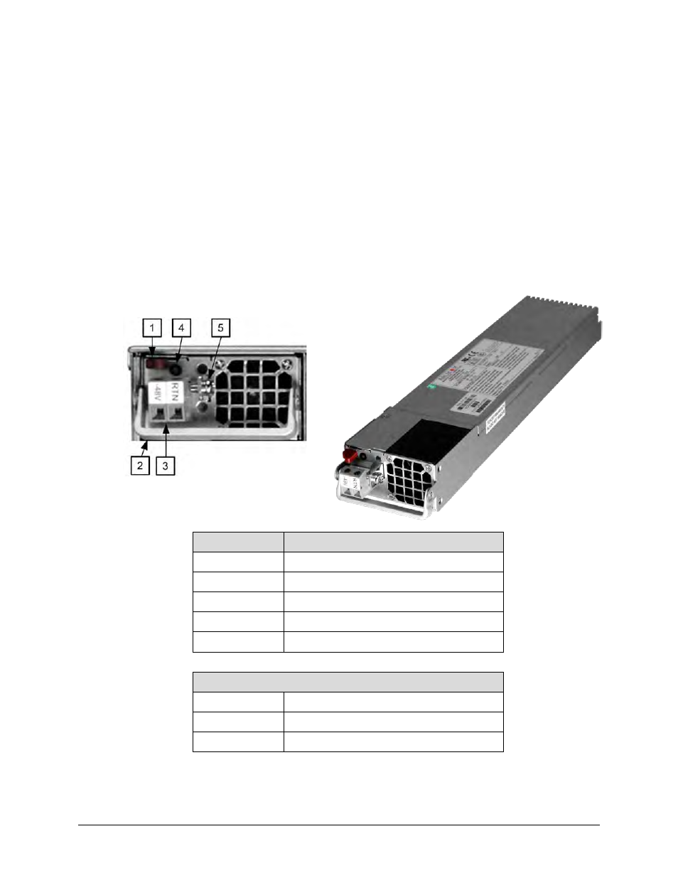
CTOG-250 Typical DC Power and Grounding Interface (Optional)
Feature
Description
1
Module Release Button
2
Module Handle
3
Power Terminal Block
4
Power LED Indicator: Green = Power applied
5
Grounding Bracket
DC Power Specifications
Input Power
TBD
Input Voltage
TBD
Connector Type
Terminal Block
Figure 3-9. Optional CTOG-250 DC Power and Ground Interface
- CDD-880 (124 pages)
- CDM-800 (130 pages)
- ODMR-840 (184 pages)
- CDM-750 (302 pages)
- CDM-840 (244 pages)
- SLM-5650A (420 pages)
- CDM-700 (256 pages)
- CDM-760 (416 pages)
- CDM-710G (246 pages)
- CDM-600/600L (278 pages)
- CDMR-570L (512 pages)
- CDM-625 (684 pages)
- CDM-625A (756 pages)
- CDD-564A (240 pages)
- CDD-564L (254 pages)
- CLO-10 (134 pages)
- MCED-100 (96 pages)
- CDMR-570AL (618 pages)
- CDM-600 LDPC (2 pages)
- BUC Power Supply Ground Cable (2 pages)
- MPP70 Hardware Kit for CDM-570L (4 pages)
- MPP50 Hardware Kit for CDM-570L (4 pages)
- CDM-625 DC-AC Conversion (4 pages)
- CDM-625 DC-AC Conversion with IP Packet Processor (4 pages)
- DMDVR20 LBST Rev 1.1 (117 pages)
- DMD2050E (212 pages)
- DMD-2050 (342 pages)
- DMD1050 (188 pages)
- OM20 (220 pages)
- QAM256 (87 pages)
- DD240XR Rev Е (121 pages)
- MM200 ASI Field (5 pages)
- DM240-DVB (196 pages)
- MM200 (192 pages)
- CRS-150 (78 pages)
- CRS-280L (64 pages)
- CRS-170A (172 pages)
- CRS-180 (136 pages)
- SMS-301 (124 pages)
- CiM-25/8000 (186 pages)
- CiM-25 (26 pages)
- CRS-500 (218 pages)
- CRS-311 (196 pages)
- CIC-20 LVDS to HSSI (26 pages)