3 ctog-250 dc power and grounding connections – Comtech EF Data CTOG-250 User Manual
Page 63
CTOG-250 Comtech Traffic Optimization Gateway
Revision 1
Back Panel Connections
MN-CTOG250
3–15
3.2.2.1.3
CTOG-250 DC Power and Grounding Connections
PROPER GROUNDING PROTECTION IS REQUIRED. The equipment must be connected
to the protective earth connection at all times. It is therefore imperative that the unit
is properly grounded, using the ground stud provided on the unit rear panel, during
installation, configuration, and operation.
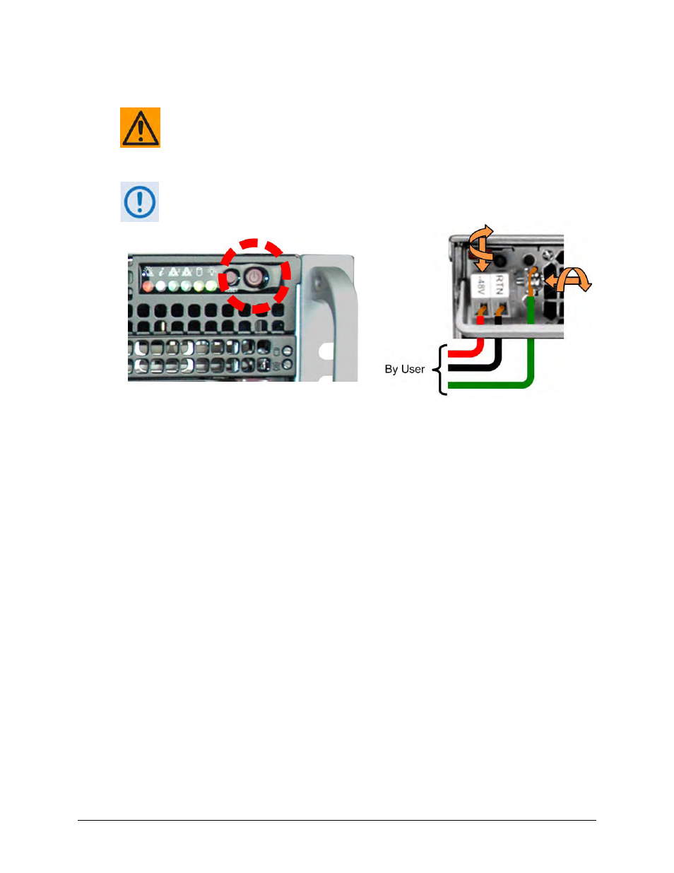
This procedure is typical for both DC Power Supply Modules.
Figure 3-10. Optional CTOG-250 DC Power and Ground Connections
To apply DC grounding and power to the CTOG-250:
• First, use a medium Phillips screwdriver to secure the ground wire to the module
grounding bracket. A Number 18 AWG minimum wire is recommended.
• Next, connect the user-supplied DC power leads to their respective terminals (-48V)
and (RTN). Number 18 AWG minimum wires are recommended. Use a small flat-bladed
screwdriver to secure each lead within its terminal block.
• Then, connect the user-supplied DC power leads to the power source.
• Finally, switch the unit ON from the chassis front panel. The module LED will light
green to indicate power to the unit is ON. The front panel LEDs will also light.