AMETEK i Series User Manual
Page 35
User Manual
i Series / iX Series
21
3.6.3 RS232C Serial Interface Connector
– J18
Table 3-4: RS232C Connector
Pin
1
N/C
2
RxD, Receive data
3
TxD. Transmit data
4
DTR, Data Terminal Ready
5
Common
6
N/C
7
RTS, Request to Send
8
N/C
9
N/C
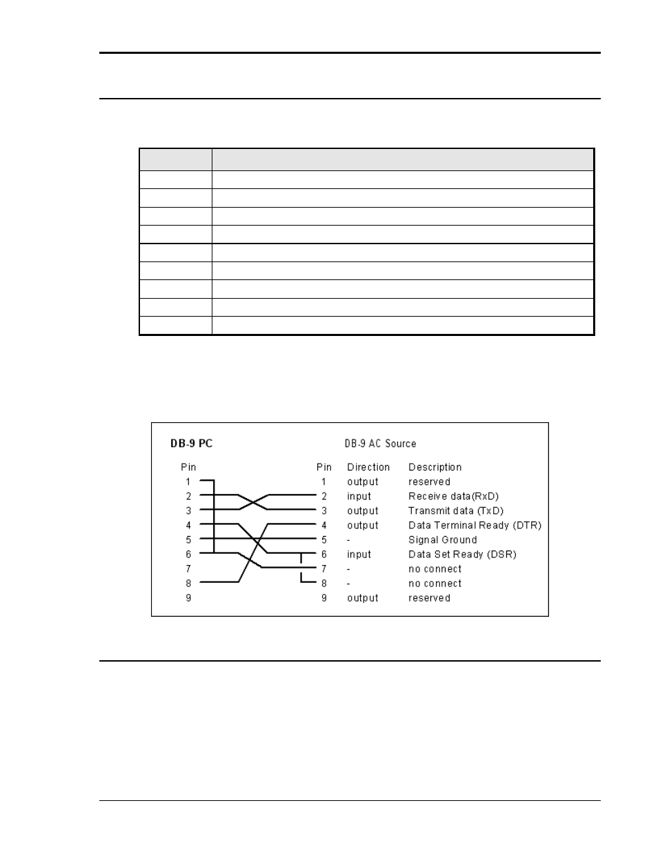
To connect the 5001iX to a PC‟s 9-pin DB9 serial port, a special RS232 cable is required. A 6
foot / 2 meter long cable (CI P/N 7000-263-1) is supplied in the iX Series ship-kit. The wiring
diagram for this cable is shown below in case a longer cable has to be constructed. Alternatively,
a generic straight thru DB9 male to DB9 female cable can be used to extend the supplied cable.
Figure 3-2: RS232C Cable for PC Connection wiring diagram.
3.6.4 I/O Option
– J58
This connector is reserved for control of the EOS option. Do not connect anything else to this
connector.