AMETEK i Series User Manual
Page 319
User Manual
i Series / iX Series
305
Controls
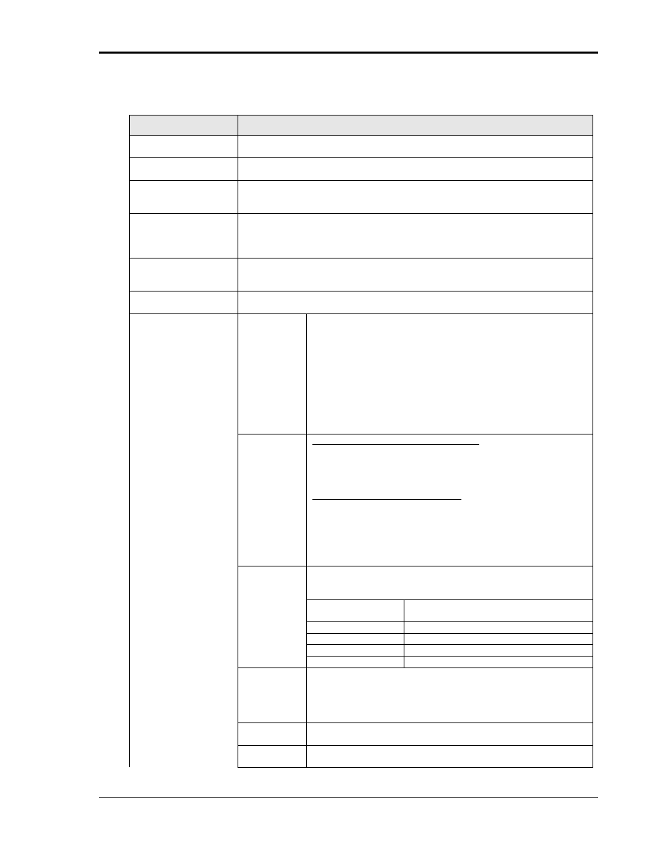
The following controls and displays are available in this window:
Control / Display
Description
Start button
Start selected transient test. This button will be disabled while a test is running
and re-enabled at the end of a test.
Abort button
Aborts a test in progress. This button will be disabled unless a test is running
and enabled as soon as a test is started.
Phase Checkbox
The Phase selections may be used to include one or more or all phases in a
test run. Only phases with a check mark will be included in a test. Phases that
are not checked remain unchanged during the test.
Graph Preview
indicator.
This text field displays the currently selected Row from the Transient
permutations grid that is shown in the graph display in the lower half of the
window. Normally, this is the row that is highlighted in the grid and/or the row
that is presently executing.
Output On/Off
Indicates the status of the output relay of the power source. Normally, the
output relay should remain closed during and between tests. To toggle the state
of the output relay, the main GUI screen must be used.
Test Selection
This section contains the settings and control to determine the type and
duration of the transient tests to be run.
Figure /
Table no.
This selection sets the type of transient to be run as either
conform Figure A or Figure B of Appendix 1.
In case Figure B is selected, the parameter table to be used
can be selected as well. Some choices may not be available
depending on the mode of operation of the power source. For
examples, Table 1.2 applies only to DC transients and will be
grayed out if the power source is in AC mode. Mode changes
can only be made from the main GUI screen.
Note that the size of the Transient permutations table will vary
depending on the Figure and Table selection made in this
control.
Type No.
For Figure A Transparency Transients:
This drop down list control contains drop times in msec. Select
the desired drop time from this list. Rise and fall times will be
set to <1 msec. Each transient will be run 5 times with a 1
second delay between transients per ABD0100.1.8 Appendix 1.
For Figure B Switching Transients:
This drop down list contains the numbers from the selected
table 1.1, 1.2 or 2. Select the number for the transient you want
to run. The GUI will automatically load all available
permutations for the selected table entry. For tables 1.1 and
1.2, these numbers are Arabic. For table 2, they are Roman
numerals.
Unom
Sets the nominal voltage at which these transients are to be
run. Recommended nominal voltages to use per Appendix 1
are shown here.
Network Type
Voltage applied at equipment terminals
(Unom)
115 VAC
104 Vrms
26 VAC
23 Vrms
Conventional DC
25.5 Vdc
NBPT DC
24 Vdc
Delay after
each
transient
This field sets the time delay between transients in seconds.
Default value is 1 second. Note that there is a small amount of
overhead from the GUI program as it reprograms the power
source between transients. This time is small compared to the 1
second delay itself however.
Repeat
Sets the number of times each transient is run. Default value is
1. For most situations, this value should be set to 1.
Retrig.
If repeat count greater than 1 is used and external trigger
source is selected, setting this check box will require only a