AMETEK i Series User Manual
Page 23
User Manual
i Series / iX Series
9
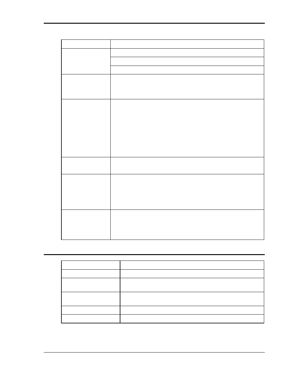
Parameter
Specification
Transient
Voltage: drop, step, sag, surge, sweep
Frequency: step, sag, surge, sweep
Voltage and Frequency: step, sweep
IEEE-488 Interface:
SH1, AH1, T6, L3, SR1, RL2, DC1, DT1
IEEE 488.2 and SCPI
Response time is 10 ms (typical)
RS232C Interface:
Bi-directional serial interface
9 pin D-shell connector
Handshake: CTS, RTS
Data bits: 7, 8
Stop bits: 1,2
Baud rate: 9600, 19200, 38400
IEEE 488.2 and SCPI
Current Limit Modes: Two selectable modes of operation.
Constant current and constant voltage with hold-off time and trip.
Function Strobe
Isolated open collector output available between pin 31 (High) and pin
14 (Low) of the System Interface connector (J22). Negative going
pulse on any programmed voltage or frequency change.
Function strobe output can be reassigned as trigger output when
running list transients.
This output requires a external DC supply and pull-up resistor.
Remote Inhibit
Also referred to as Remote On/Off. Digital input available on pin 36
and pin 27 (D-Common) of the System Interface connector (J22). The
Remote inhibit input can be used to open the output relay. The output
relay state is not latching so will return to the closed state when the
input is removed.
2.1.8 Unit Protection
Input Overcurrent:
Circuit breaker with shunt trip control.
Input Overvoltage:
Automatic shunt trip of input circuit breaker.
Input Overvoltage
Transients:
Surge protection to withstand EN50082-1 (IEC 801-4, 5) levels.
Output Overcurrent:
Adjustable level constant current mode with a maximum set point
between 0% and 10% above programmed value.
Output Short Circuit:
Peak and rms current limit.
Overtemperature:
Automatic shutdown.