5 routine measurement calibration – AMETEK i Series User Manual
Page 131
User Manual
i Series / iX Series
117
6.5 Routine Measurement Calibration
Connect the test equipment to the power source as shown in Figure 6-2. If the power system is
a multi-phase system with one controller, the DVM for calibrating the measurement voltage
should always be connected to the Remote Sense connector (TB3) on the Phase A power
source.
The shunt must be connected to the power source as shown in Figure 6-2. If the Current
measurement can‟t be successfully performed, adjust the Current Measurement Pot. This
adjustment is described in the Non-routine Calibration section of this manual. If the DC current
measurement displays more than 70 counts on the display, perform the non-routine current
monitor adjustment.
Connect the load to the output. Use the 10 milliohm current shunt in series with the load to
measure the AC and DC load current. When programming a DC load always program the output
voltage to 0 volts before changing the output load. This will prevent load switch contacts from
being damaged.
To calibrate all measurement functions, the desired value for the measurement value of current
or voltage must be entered for the corresponding calibration value. Make the indicated
adjustments by typing in the desired display value. This should be the value indicated by the
external DVM. If a 10 milliohm current shunt is used for current, 300 millivolts represents 30
amps.
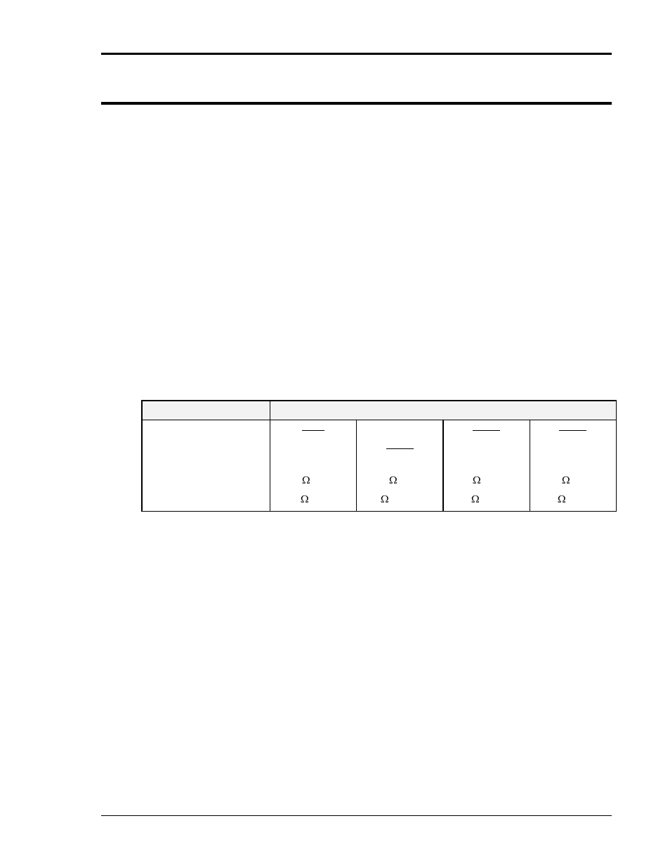
The Measurement Calibration Table is a summary of the measurement calibration procedure.
The following text is a detailed explanation of the procedure.
PARAMETER
POWER SYSTEM
3001
5001
10001
15001
15003
AC Current Full-Scale
6.8 , 3KW
4.1 , 5KW
2.1 , 10KW
1.35 , 15KW
DC Current Full-Scale
13.5 , 1.5KW
8 , 2.5KW
4 , 5KW
2.7 , 7.5KW
Table 6-2: Calibration Load For Each Phase