AMETEK i Series User Manual
Page 130
User Manual
116
i Series / iX Series
150 VDC Range Volt Zero:
Press the PROGRAM key. Select VOLT RANGE and program the 150 VDC range with the
shuttle. Go to the OUTPUT CAL screen and adjust the VOLT ZERO for 0.0 0.005 volts DC on
the output.
150 VDC Range + Full-scale:
Program +120.0 volts. Go to the OUTPUT CALIBRATION screen and adjust the VOLT FS
parameter for an output voltage of +120.0 ±0.05 volts DC.
150 VDC Range - Full-scale:
Program -120.0 volts. Go to the OUTPUT CALIBRATION screen and adjust the VOLT FS
parameter for an output voltage of -120.0 ±0.05 volts DC.
For a 9003iX or 15003iX 3-Phase power system with one controller, repeat the preceding steps
for the Phase B and C outputs. Press the PHASE key to select the output to be calibrated.
Monitor the output of the respective phase by moving the HI input of the Digital Multimeter. The
LO input should remain connected to the common LO of the sense connector, TB3.
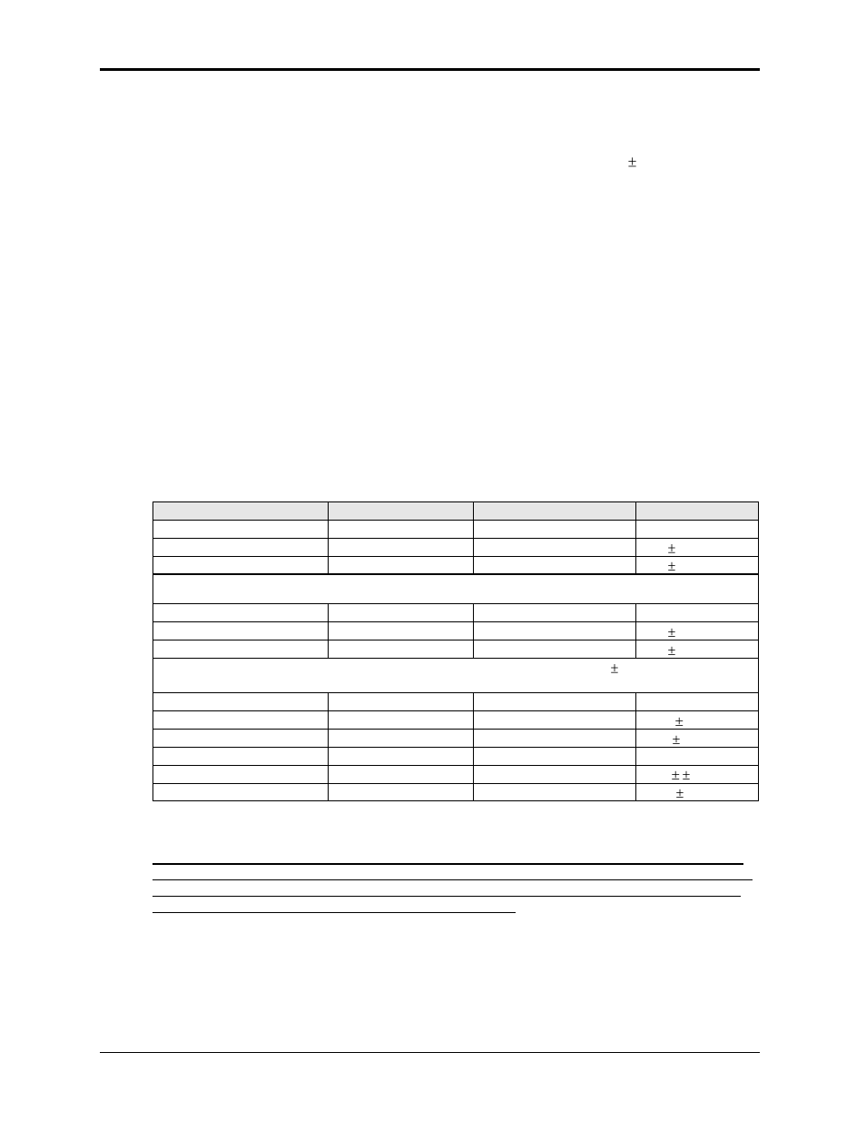
The following Table is a summary of the preceding calibration steps.
Program the following values in the table and make the adjustments in the OUTPUT
CALIBRATION screen. Select the phase to be calibrated by pressing the PHASE key.
TITLE
PROGRAM VALUES
CALIBRATION VALUE
ADJUST TO
150 VAC range DC Zero
150 range, 0.0 V
VOLT ZERO
0 ± 5 mv DC
150 VAC range Volt FS
120.0 V, 60 Hz
VOLT FS
120 0.05 VAC
150 VAC range Volt Hi Freq
120.0 V, 400 Hz
V HI FREQ
120 0.05 VAC
Repeat the adjustments at 60 and 400 Hz until the output is within ± 0.05 volts
300 VAC range DC Zero
270 range, 0.0 V
VOLT ZERO
0 ± 5 mv DC
300 VAC range Volt FS
240.0 V, 60 Hz
VOLT FS
240 0.05 VAC
300 VAC range Volt Hi Freq
240.0 V, 400 Hz
VOLT HI FREQ
240 0.05 VAC
Repeat the adjustments at 60 and 400 Hz until the output is within 0.05 volts
150 VDC range DC Zero
135 range, 0.0 V
VOLT ZERO
0 ± 5 mv DC
150 VDC range Volt +FS
+120.0 V
VOLT FS
+120 0.05 VDC
150 VDC range Volt -FS
-120.0 V
VOLT FS
-120 0.05 VDC
300 VDC range DC Zero
270 range 0.0 V
VOLT ZERO
0 ± 5 mv DC
300 VDC range Volt
+240.0 V
VOLT FS
+240 0.05 VDC
300 VDC range Volt -FS
-240.0 V
VOLT FS
-240 0.05 VDC
Table 6-1: Output Calibration Table
For a multi-phase power system that uses one controller, 9003iX or 15003iX, repeat paragraph
6.4 for each phase. Move the external multimeter to the phase being calibrated. Make sure that
the phase being calibrated is programmed to the correct voltage. While viewing the calibration
screen, press the PHASE key to select the respective key.