AMETEK i Series User Manual
Page 197
User Manual
i Series / iX Series
183
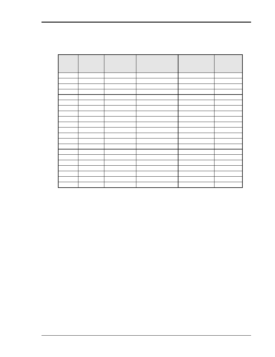
RUN ALL
The RUN ALL selection will cause the following automated test sequence suggested by the
standard to be run:
Step
Output in
% of U
T
No of Cycles
Start angle
(degrees)
Repeat # times
Delay
between
repeats (s)
1
0
0.5
0
3
10
2
0
0.5
180
3
10
3
0
1
0,45,90
3 at diff ø
10
4
0
5
45,90,135
3 at diff ø
10
5
0
10
90,135,180
3 at diff ø
10
6
0
25
180,225,270
3 at diff ø
10
7
0
50
270,315,0
3 at diff ø
10
8
40
0.5
0
3
10
9
40
0.5
180
3
10
10
40
1
0,45,90
3 at diff ø
10
11
40
5
45,90,135
3 at diff ø
10
12
40
10
90,135,180
3 at diff ø
10
13
40
25
180,225,270
3 at diff ø
10
14
40
50
270,315,0
3 at diff ø
10
15
70
0.5
0
3
10
16
70
0.5
180
3
10
17
70
1
0,45,90
3 at diff ø
10
18
70
5
45,90,135
3 at diff ø
10
19
70
10
90,135,180
3 at diff ø
10
20
70
25
180,225,270
3 at diff ø
10
21
70
50
270,315,0
3 at diff ø
10
Table 9-19: Dips and Interruptions Tests Performed During RUN ALL
The user can change the NOMINAL Ut voltage for this. The RUN ALL Command line will change
to ABORT during the test. Selecting ABORT and pressing the ENTER key will terminate the test
at any time and the output voltage will return to the nominal value.
RUN SINGLE
RUN SINGLE command will run a single test once. The Dip or Interrupt test is defined by the DIP
TO, NO CYCLES, and START ANGLE parameters. These parameters must be set before
starting the test. The following is a description of these parameters.
DIP TO:
The dip voltage level as a percentage of the nominal voltage.
NO CYCLES:
The dip duration in cycles.
START ANGLE:
The start phase angle of the dip
Note: After each individual run, a 10 second delay is inserted.