AMETEK i Series User Manual
Page 136
User Manual
122
i Series / iX Series
5. Calculate the resistive and inductive component R and L using the formulas shown in Table
6-8. (Alternatively, use the 16 bit CIGUI.)
6. Enter these values, in the OUTPUT CAL screen for the IMP. REAL MIN and IMP. REACT
MIN value respectively. Make sure the correct phase is selected or use the PHASE key if
not.
7. Remove or turn off the load.
8. From the MENU 3 screen, select OUTPUT IMPEDANCE. Press the PHASE key to select
the phase to be calibrated. Program the output inductance to 796 uH and the resistance to
400 mOhms.
9. Select the Calibration, Output screen and move the cursor to the IMP REAL FS field.
Measure the R and L by removing and applying the load as described before and calculating
the R and L using the formula's in Table 6-7.
Adjust the resistive output impedance using the shuttle until the measured output is as close
as possible to 400 mOhm. Make sure the correct phase is selected or use the PHASE key if
not. Do the same with the IMP REACT FS field. Note that the adjustment range for R is 0 to
100, for L is 0 to 300.
10. If there is not enough range in the full-scale calibration coefficient for either resistive or
inductive portion, it may be necessary to tweak the adjustment pots on the iX controller.
These pots were originally adjusted at the factory and normally do not have to be adjusted
again. The Full Scale calibration coefficients should have enough adjustment range. Double
check the connections and phase measurements if this is not the case to make sure the
measurement readings you get are indeed correct.
If it is necessary to adjust the pots, see Table 6-7 for the corresponding pot designators. The
top cover has to be removed to access these pots. They are located along the top edge of
the controller board(s). Adjustments for phase A are on the phase A/CPU board (5100-707),
adjustments for phase B and C are on the phase B/C board (7000-722).
11. Repeat steps 2 through 10 for phase B and C.
Phase / Board Assembly #
R resistive
Xl inductive
Phase A /CPU (5100-707)
R121
R122
Phase B (7000-722)
R112
R111
Phase C (7000-722)
R114
R115
Table 6-7: Programmable Z adjustment pots
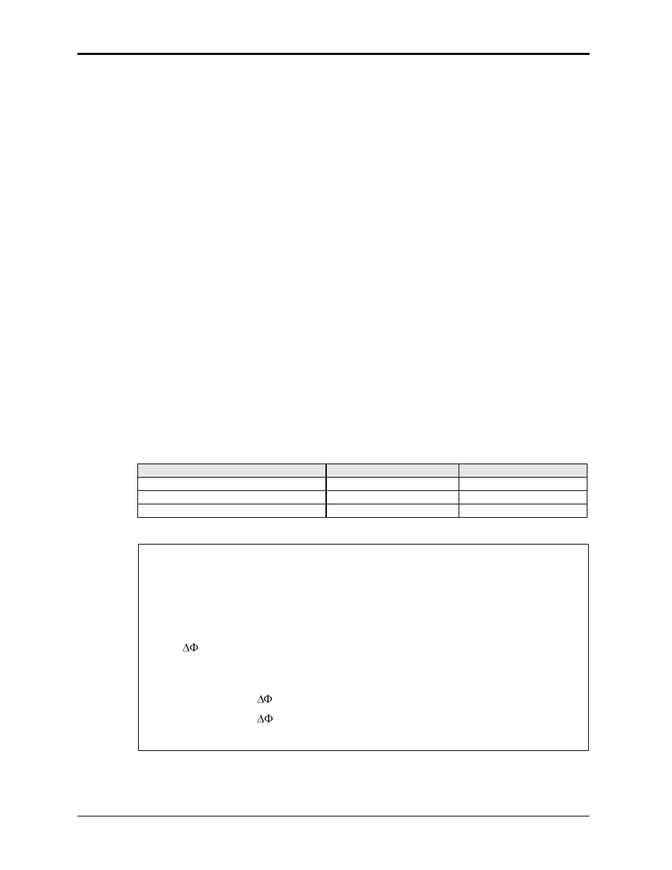
Definitions:
V
NL
= Measured RMS voltage under no load.
V
L
= Measured RMS voltage under load
I = Measured RMS current.
F = Source frequency (50 Hz).
= Phase angle shift between load and no load conditions. Record phase angle
from phase meter under NL and L condition and determine phase shift.
Formulas to calculate R and L component of output impedance:
R = ( V
NL
* cos(
) - V
L
) / I
X
L
= ( V
NL
* sin(
)) / I
L = X
L
/ (2 * Pi * F)
Table 6-8: Formulas to calculate R and L