6 non-routine calibration – AMETEK i Series User Manual
Page 134
User Manual
120
i Series / iX Series
6.6 Non-Routine Calibration
The non-routine calibration involves removing the top cover from the power source. Remove the
line power from the power source before removing the top cover. Most of the adjustments are on
the Current Limit Assembly. One adjustment is on I/O Board Assembly. Refer to Figure 6-3 for
the location of the adjustments.
6.6.1 Power Source Gain Adjustment:
To make this adjustment the top cover must be removed and voltages must be monitored at
various test points. The test point used depends upon the phase to be adjusted. Refer to Table
6-4 for the test point. The adjustment is R14 on the Current Limit Board. Refer to Figure 6-3 for
the location R14 on the Current Limit Board.
On the Phase A/CPU board, monitor TP31 with respect to TP1. Program +300 VDC. Adjust
R14 on the Current Limit Board so that the voltage at TP31 is 13.0 VDC. Program -300 VDC.
Check voltage at TP31. If it is greater than 13.0 VDC, adjust R14 for 13.0 VDC. If it is less than
13.0 VDC, do nothing.
For multiphase power systems with one controller, 15003iX, the adjustment for Phase B and C
must be made to R14 on the Current Limit Board for the power source of the respective phase.
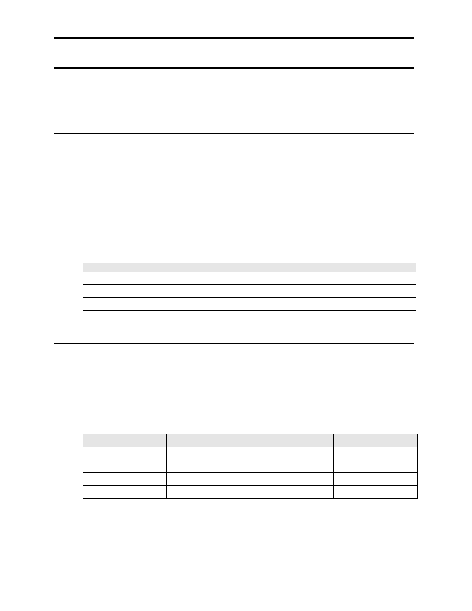
PHASE
TEST POINT (Controller in Phase A Power Source)
A
TP31 to TP1 CPU/Phase A
B
TP5 to TP1A Phase B/C
C
TP6 to TP1A Phase B/C
Table 6-4: Gain Adjustments
6.6.2 Current Limit Calibration:
Program the output to the 150 VAC range and the current limit to IPROG in Table 6-5. Program
the output to the constant current mode (CC). Apply full load for the 150 volt range to the output.
Adjust R38 on the Current Limit Board for an output current of ISET in Table 6-5.
If the current is less than the set value, observe the Front Panel Overload Indicator for each
power source. Adjust R38 on the Current Limit Board of the Power Sources with the Indicator
illuminated. Adjust R38 just to the point the output current is on 103% above the programmed
value.
MODEL
IPROG
ISET
R LOAD (ohms)
5001, 15003
30
31.0
4.5, 5KW
10001, 30003
90
63.0
2.25, 10KW
15001
90
93.0
1.5, 15KW
3001, 9003
18
18.6
8, 3KW
Table 6-5: Current Limit Calibration
Repeat this adjustment for the Phase B and Phase C power sources of a 15003 power system.