AMETEK i Series User Manual
Page 123
User Manual
i Series / iX Series
109
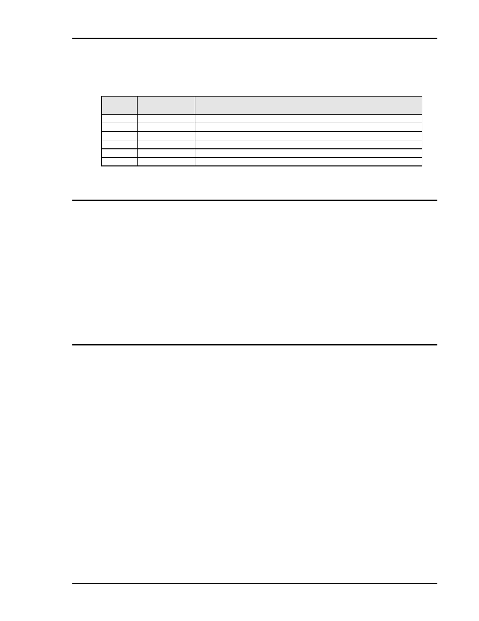
There are six LED indicators on the logic board. Their positions are shown in Figure 5-4. The
LED functions are listed in Table 5-1.
Table 5-1
: Logic Board LED’s
LED#
FUNCTION
COMMENTS
DS2
+15V
+15V logic supply
DS3
-15V
-15V logic supply
DS4
+8V
+8V oscillator supply
DS7
+24V
+24V supply for relays and logic.
DS5
PARALLEL
LED should be lit when units are paralleled and K1 is closed.
DS1
FAULT
LED is lit - unit normal. No light indicates pwr. stage failed
5.8 AC Power Board
The AC power assembly takes a 250V/500V DC input and generates a 150V/300V AC direct
c
oupled output. The AC power amplifier is a full bridge inverter with three paralleled IGBT‟s in
each leg for a total of twelve IGBT‟s. The switching frequency of the bridge is 37.5 kHz and this
frequency is smoothed out by two inductors that are mounted behind the input/output board and
several smoothing capacitors on the AC power board to provide a precision low frequency (16-
500 Hz) output. (See Figure 5-3 and Figure 5-5)
Three isolated 18V supplies provide power for the gate drives. The 18V is regulated down to
15V by three TO220 regulators that are mounted on three discrete sheet metal heat sinks. If the
15V is in regulation, an LED will be lit in front of each heat sink. There is a red, a green and an
orange LED, one for each supply. The other four green LED‟s will be lit when there is gate drive
present at the IGBT‟s. If the green LED‟s are not lit there will be no gate drive and hence no
output.
5.9 Input/Output Board
The input/output board holds a lot of the large components and provides interconnection
between the AC input, the DC-DC board, the AC power board and the output without the use of
heavy cables. The output relay and the output current metering circuit are also mounted on this
board. The output AC inductors, the DC-DC transformer and the DC output choke are mounted
on brackets behind the input/output board. These brackets also provide support for the
input/output board.