Power/input-output cable – KEYENCE IG Series User Manual
Page 29
2-1 Mounting and Wiring the Sensor Amplifier
2-7
IG-E
2
In
s
ta
lla
tion
a
nd C
onnection
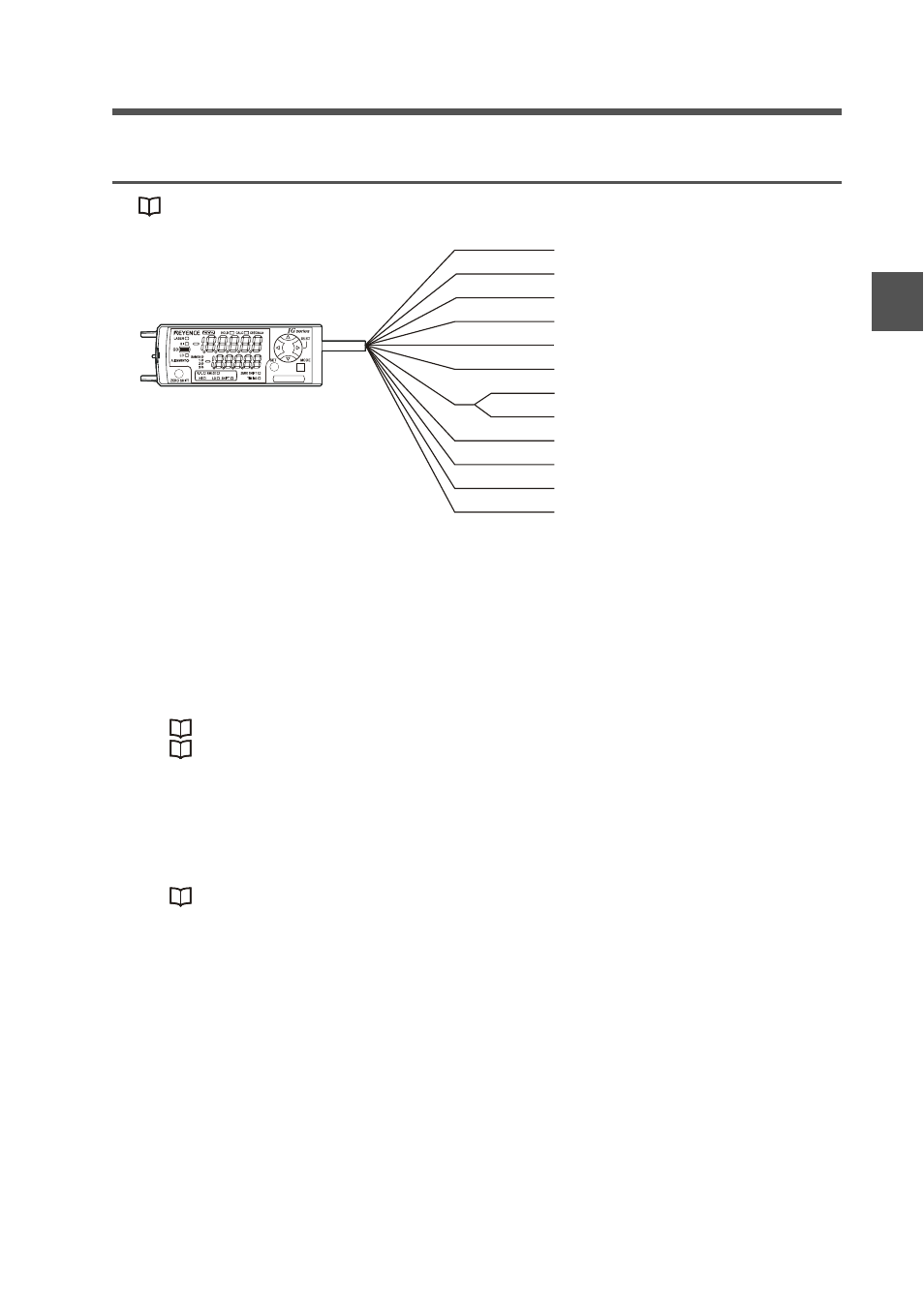
Power/Input-output cable
"Output Circuit Diagram" (page 5-4)
*1 IG-1050/IG-1550 (expansion units) do not have brown, blue or light blue wires.
Power is supplied to the expansion units through IG-1000/IG-1500 (main unit).
*2 The analog output can be set to either "When the power is turned on for the first time"
or "When performing the initial reset".
• Not used (OFF)
• 0 to 5 V
• -5 to 5 V
• 1 to 5 V
• 4 to 20 mA
"3-1 Operation When the Power is Turned on for the First Time" (page 3-2)
"3-5 Initial Reset (Initialize)" (page 3-10)
*3 The external input can be selected among the following in addition to the above.
• Bank A input
• Bank B input
• Laser emission stop input
• Not used (OFF)
Gain input can be selected only for the external input 4.
"11. External input" (page 4-33)
Brown
Blue
Black
White
Gray
Light blue
Orange
Shield
Pink
Yellow
Pink/Purple
Purple
Green
10 to 30 VDC
0 V
HIGH judgment output
LOW judgment output
GO judgment output
Analog output +
Analog output GND
External input 1 (Zero shift input)
External input 2 (Reset input)
External input 3 (Timing input)
External Input 4 (Gain input)
Edge check output
*1
*1
*1
*2
*2
*3
*3
*3
*3