Sensor amplifier wiring, Sensor amplifier wiring -6 – KEYENCE IG Series User Manual
Page 28
2-1 Mounting and Wiring the Sensor Amplifier
2-6
2
In
s
ta
lla
tion
a
nd C
onnection
IG-E
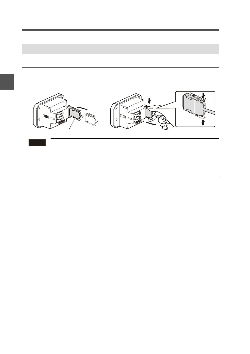
Connecting power/Input-output cable (only for panel mount type)
Connect the power/input-output cable to the panel mount type main unit and connect the
input-output cable to the expansion units.
Sensor Amplifier Wiring
Note
• The number of core wire of power/input-output cable for the main unit
is 12, and the number of core wire of Input-output cable for the
expansion units is 8.
• Power for the expansion units is supplied from the main unit.
• If the input-output is not used for the expansion units, cut the cable at
the connector base or terminate the wires properly for future use.
Power/Input-output cable
To attach
To remove
See also other documents in the category KEYENCE Sensors:
- LR-TB2000 Series (12 pages)
- LR-TB5000 Series (12 pages)
- LR-ZB250AN/AP (4 pages)
- LR-ZB250AN/P (3 pages)
- LR-ZBxN/P Series (3 pages)
- LR-ZBxxB (3 pages)
- OP-85135 (1 page)
- PZ-G Series (2 pages)
- PZ-V/M (2 pages)
- PS-N10 Series (12 pages)
- PX-10 (10 pages)
- CZ-V21A(P) (10 pages)
- CZ-K1(P) (8 pages)
- CZ-V1 (8 pages)
- FS-N10 Series (6 pages)
- FS-N10 Series (116 pages)
- FS-N15CN (1 page)
- FU-93(Z) (2 pages)
- FU-V Series (2 pages)
- FS-V30 (6 pages)
- FU-A40 (1 page)
- NU/FS-N Series (16 pages)
- FS-V33(P) (8 pages)
- FS-V21 (4 pages)
- FS-V22 (4 pages)
- FS-V11(P) (4 pages)
- FS-V1(P) (4 pages)
- LV-N10 Series (12 pages)
- LV-N10 Series (112 pages)
- LV-S62 (1 page)
- OP-84350 (1 page)
- LV-SA (10 pages)
- LV-SB (12 pages)
- OP-87305 (1 page)
- LV Series (10 pages)
- LV-B102 (1 page)
- EV-108M(U) (1 page)
- EZ Series (1 page)
- EM Series (1 page)
- ES-M1(P) (3 pages)
- EX-V Series (120 pages)
- EX-500(W) Series (16 pages)
- GV Series (10 pages)
- IA Series (8 pages)
- LB-1000(W) (24 pages)