Holtgreven GSE-355 I.S. User Manual
Page 43
34
M
AX
V
OLTAGE
Active mode Tx current loop provides a driving voltage of 12v. This will allow 20 mA current flow with up to a 600
ohm load. Passive mode will work with an external driving voltage of up to 50v.
C
ONNECTIONS
The field connections to the 20 mA circuitry will be made at the main board’s comm connector, i.e. the lever connector
on the ‘60-Series’ products and the Model 350/355 Stainless Steel version and at the ‘D’ connector on the Model 350
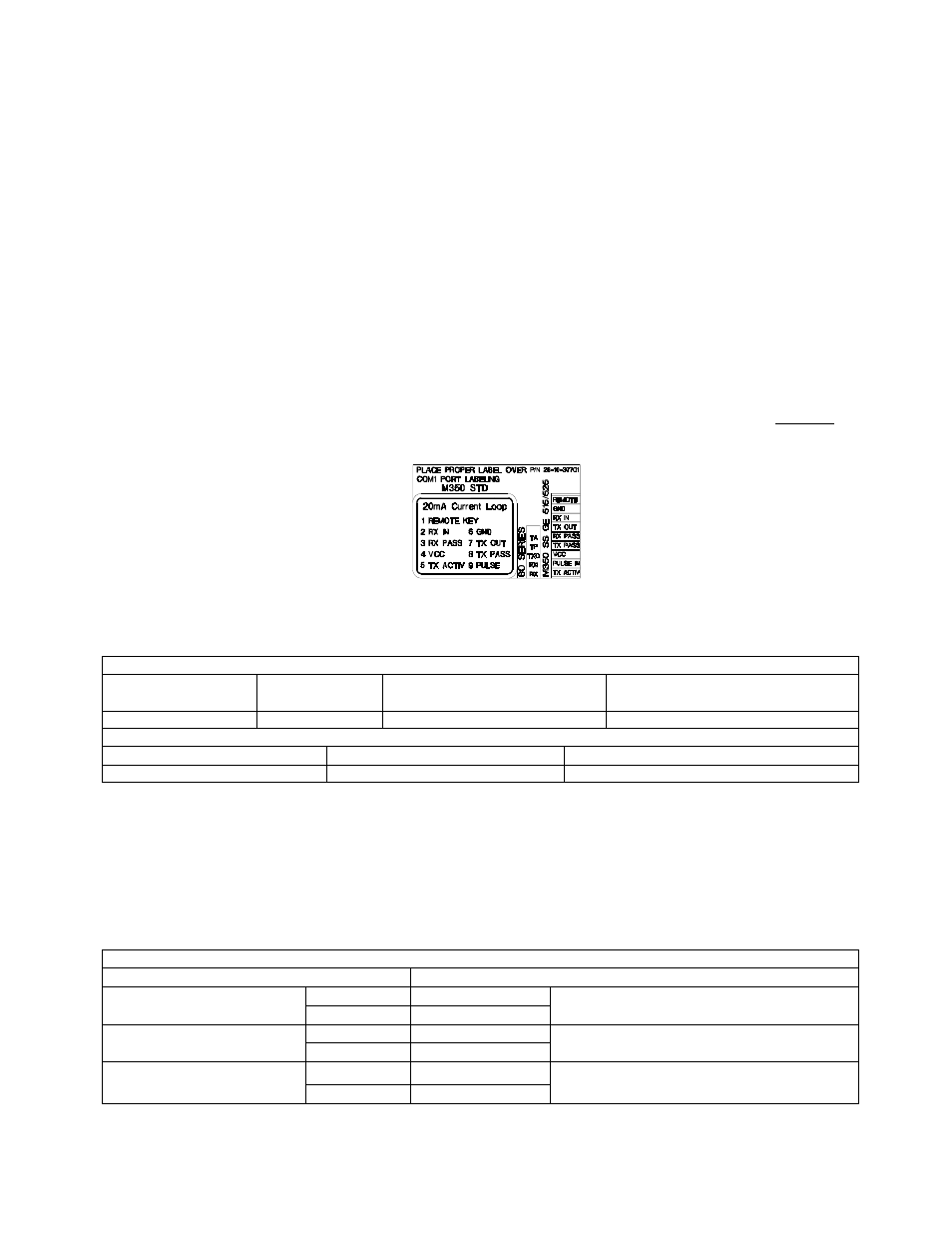
Zinc Die Cast unit. A 3-part label is supplied with the option to re-label the connections on the main circuit board. The
appropriate part of this label should be applied over the existing comm port markings on that indicator. Below is a
copy of the label drawing.
C
ABLE
The length for the current loop is 1000 ft. maximum. This is for the entire loop, not from device to device. Example: 1
transmitter and 1 receiver can have a maximum of 500 ft. of 2 conductor cable between them.
Place this label over the COMM PORT pin designations.
Table 9: 20 mA Label Terminology
TRANSMITTER CONNECTIONS
Indicator Transmitter
Output
Transmit current input, Active
Transmit current input,
Passive
350 SS & ZDC
TX OUT
TX ACTIV
TX PASS
RECEIVER CONNECTIONS
Indicator
Receiver current output
Receiver current input
350 SS & ZDC
RX PASS
RX IN
C
ONNECTED
D
EVICES
While 20 mA current loops can allow for more than one transmitter and/or receiver, the indicator and/or option board
do not include any address recognition or collision avoidance and/or detection to promote this usage. If the 20-mA
loop is intended to be used in this manner, proper planning for these issues is required
.
Table 10: Connecting to External Devices
Typical Installations
Model 350/355
External Device
TP RX+
Passive 20 mA Output
TXO RX-
Active 20 mA Input
RXI RX+
Passive 20 mA Input
RX RX-
Active 20 mA Output
TXO RX+
Active 20 mA Output
TA RX-
Passive 20 mA Input