20 ma current loop option – Holtgreven GSE-355 I.S. User Manual
Page 42
33
20 mA Current Loop Option
Description: This option will convert the comm port of the indicator to a 20 mA current loop instead of an RS-232.
This is a digital communication signal and should not be confused with a 4 to 20-mA (or 0-20 mA) which are analog
output signals. The intended use is primarily printers and scoreboard displays.
Mounting/Installation: This option will mount into the socket for the comm port RS-232 chip on the main board.
This option will exclude the use of the RS-485 option board. (I.e. only the RS-485 OR the 20 mA option can be
installed into an indicator). Three snap-in stand-offs are included with the board to secure it to the main board beneath
it.
I
NSTALLATION
:
1. Open the indicator and gain access to the main board.
2. Remove the RS232 IC from its socket. (See table for location)
3. Remove the white wire jumper. (See table for location)
4. Snap the plastic spacers into the three mounting holes.
5. Gently press the option board into the socket.
6. Apply the proper portion of the included sticker to the COMM port. The label will either go over the silk screen on
the board or on the rear cover. (See table for location)
7. Reassemble the indicator.
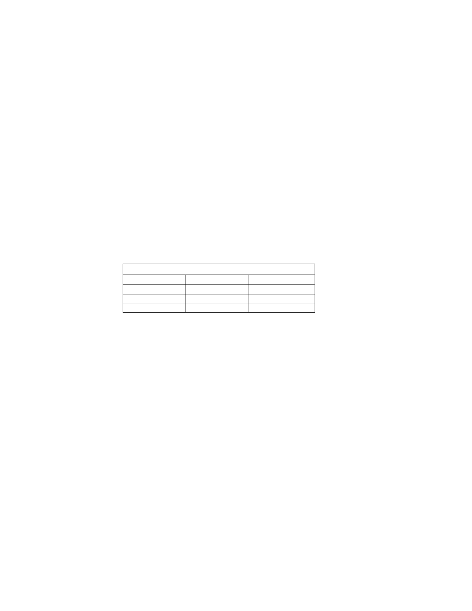
Location of Components to Remove
350 Die cast
350 SS/355
RS232 IC
U6
U6
Jumper E2
E2
Label Location
Rear Cover
J6
B
I
-
DIRECTIONAL
Both the transmit output and the receive input of the indicator are available as 20 mA signals. None of the handshake
signals are supported for the 20-mA current loop operation.
B
AUD
Only baud rates of 9600 baud and less are supported.
A
CTIVE
/P
ASSIVE
The Tx output may be used as an active or passive output from the indicator. Either active or passive is chosen
depending upon which terminals are used for the connections. In active mode the indicator supplies the current. In
passive mode, the external device supplies the current. The Rx input is available in passive mode only.
I
SOLATION
The input and output are electrically isolated from the main board as well as earth ground and each other, for both
passive and active modes of operation. Isolation is a minimum of 1000v.