Holtgreven GSE-355 I.S. User Manual
Page 40
31
N
ETWORK
C
ONNECTIONS
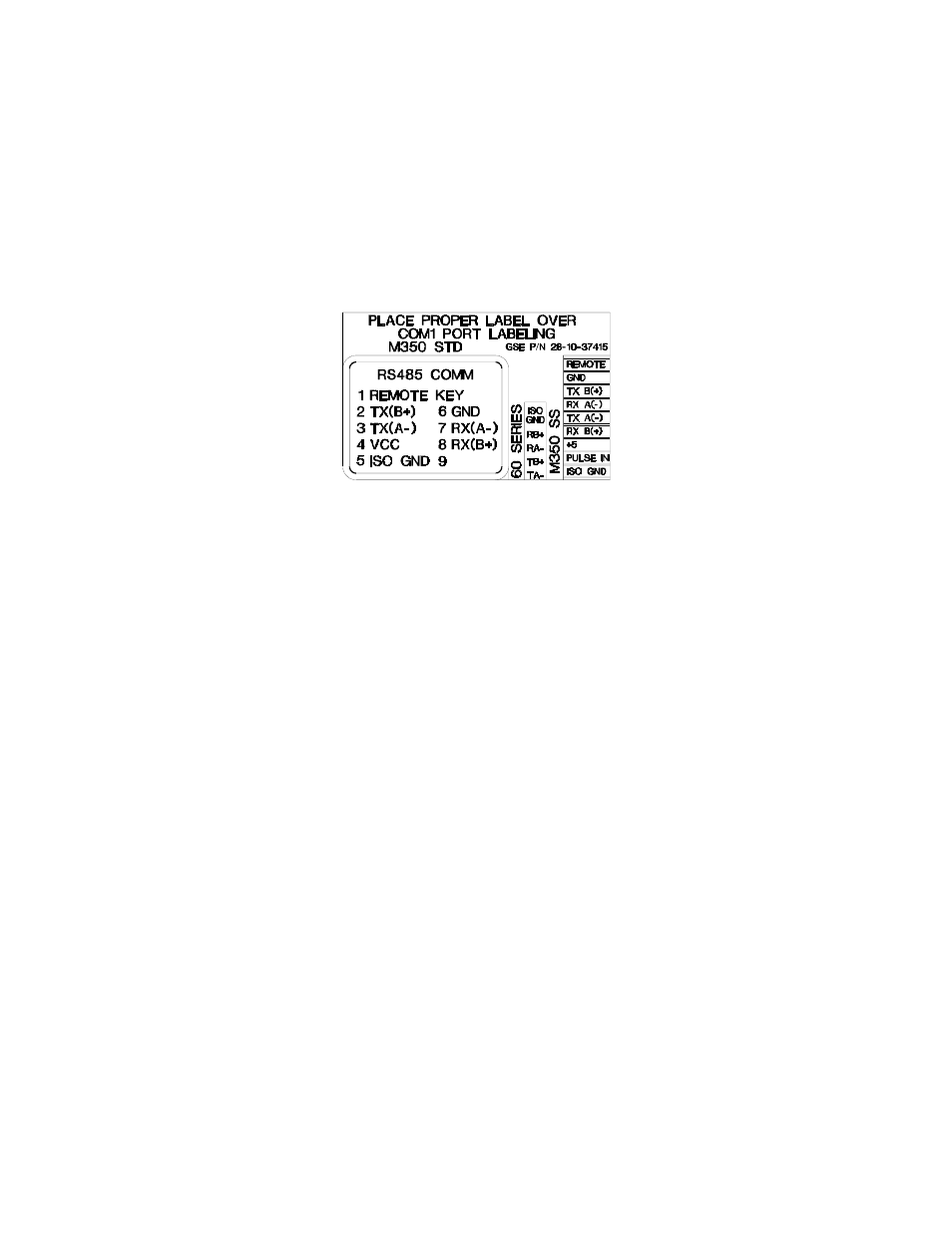
Apply the supplied label over the appropriate COMM PORT pin designations.
On the stainless steel enclosure, apply the label marked Model 350/355 SS to the main board (J6). Position the label so
the REM (remote) on the main board is covered with the REM (remote) of the supplied label. The new label will
redefine all of the other pin designations.
On the die cast enclosure, apply the label marked Model 350 STD to the outside of the enclosure. The supplied label
RS485 COMM should completely cover the RS232 COMM portion of the factory installed label.
Place this label over the COMM PORT pin designations.
H
ALF
D
UPLEX
(2-
WIRE
)
Installing jumpers 1, 2 and 4 on the RS-485 option board electrically connects pin RX B(+) to pin TX B(+), and pin RX
A(-) to pin TX A(-) on the option board. This effectively provides two + and two - pin connections, enabling easy
connection of network lines in parallel from device to device without having to position two wires into the same lever
socket. A B(+) line from each device on the network should be connected in parallel to the next device on the network.
This is also true for all A(-) lines.
The units inside the two end-points of the network loop will utilize both A(-) pin connections and both B(+) pin
connections. The units at the end-points of the network will utilize only one A(-) pin connection and one B (+) pin
connection.
F
ULL
D
UPLEX
(4-
WIRE
)
Removing jumpers 1, 2 and 4 on the RS-485 option board requires that the transmit and receive lines be wired
independently of one another. The RX B(+) and RX A(-) receive lines must be wired in parallel to the next device’s RX
B(+) and RX A(-) receive lines , and the TX B(+) and TX A (-) transmit lines must be wired in parallel to the next
device’s TX B(+) and TX A(-) transmit lines.
In order to connect network lines in parallel from device to device it is necessary to position two wires into the same
lever socket. This requires that the wire used to build the network be 24 AWG or smaller to allow both wires to fit into
the same lever socket.
B
OTH
H
ALF
D
UPLEX AND
F
ULL
D
UPLEX
The network boards on both end-points should install jumper 3 on the RS-485 option board to engage the 120
Ω
termination resistor (R8). The boards between the two end-points should remove jumper 3 on the RS-485 option board.
The isolated ground (ISO GND) should be connected in parallel from unit to unit. A shielded twisted two pair cable is
recommended throughout the network.