Holtgreven GSE-355 I.S. User Manual
Page 28
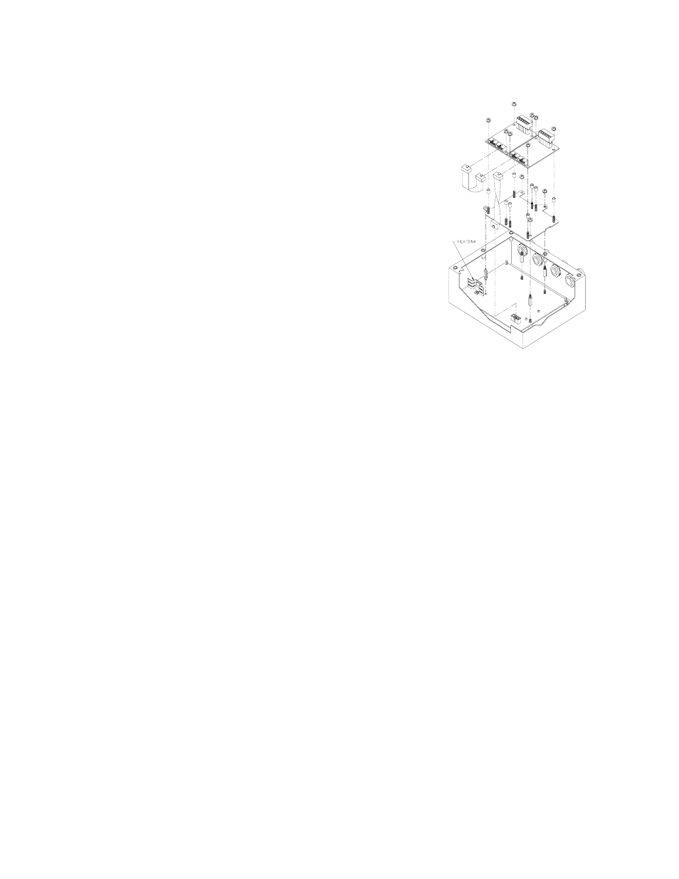
19
To install the Analog Output Model (350 Stainless Model and 355):
1. Open the indicator.
Remove the eight screws from the back of the unit.
2. Locate the three studs and one thru-hole on the 350 main board
that the option mounting bracket will be attached to. See Figure
20. Remove the nuts from the three studs on the main board.
It may help to position the option mounting bracket over the 350
main board to locate the three studs and one thru-hole.
3. Install the nylon stand-off supplied with the option bracket kit into
the thru-hole on the option bracket. See Figure 20.
The thru-hole is located on the option bracket, towards the center
of the board, on the irregular flanged section (a smaller hole than
the others on the bracket) that would be positioned towards the
power supply regulator (U11) with a flanged heat sink on it.
4. Install the three hex stand-offs onto the studs on the main board.
Tighten the stand-offs gently with a 6 mm hex nut driver.
5. If this is the first option card, attach the loose end of the cable to
the serial I/O connector (J7) on the main board. Let the card gently
hang over to the outside of the enclosure until mounting. J7 is a 10-
pin polarized connector.
This step is not necessary if this is the second card installed.
6. Position the nylon stand-off (attached to the bracket) into the hole on the main board while routing the threads
of the other hex stand-offs thru the holes on the bracket, while pressing down over the nylon stand-off until it
snaps into place.
Line-up the three other hex stand-offs into the bracket thru-holes first before securing the nylon stand-off into
the main board thru-hole.
7. Secure the bracket into position with the hex nuts supplied with the kit. Do not over tighten.
8. Place one set (four pieces) of the nylon sleeve type stand-offs onto the four studs of the option bracket. Place
the Analog Output Module, component side up, onto the nylon sleeve stand-offs. Install four hex nuts and
secure gently.
Select the four studs closest to the (J7) connector of the main board to add the four sleeve stand-offs. Be sure
the cable is already attached to (J7) on the main board before installing the card. Also be sure the cable is
attached to the right-most connector (J3) (as viewed from the component side of the option board). The second
connector (J1) is for ‘daisy-chaining’ another option card. The additional mounting hardware is supplied with
the option bracket kit. This hardware should be saved for future use if not being used.
9. Route the analog cable through the available strain-relief.
Make sure to connect cable conductors to the proper terminals before closing the unit.
10. Reinstall the back cover. Tighten the eight screws securely to create a good seal.
Be sure to avoid ‘pinching’ the cable between the housing halves.
Figure 20: Option Board Installation
(Stainless Model 350/355)