Holtgreven GSE-355 I.S. User Manual
Page 38
29
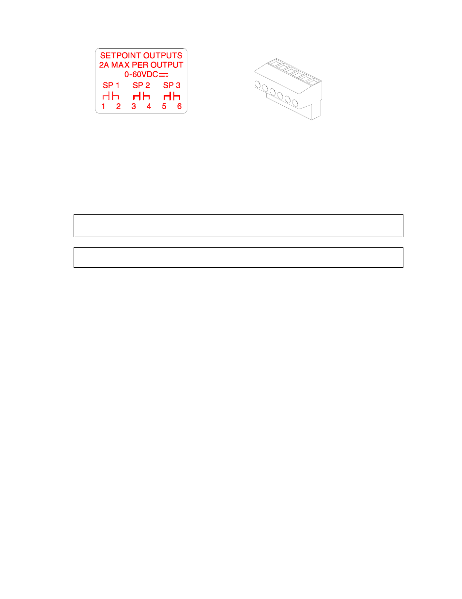
Place this label above the setpoint card knockout (die cast)
Figure 23: Wire the option connector in accordance
with the label (left to right)
(Stainless steel model) Cut off the text “SETPOINT OUTPUTS” from the label and place it on the connector shown in
Figure 23 (apply to the area just under the field external wire terminals).
S
ETPOINT
B
OARD
D
IAGNOSTIC AND
T
EST
P
ROCEDURES
This test procedure affects the setpoint output. Be sure to disconnect all peripheral devices attached to the
setpoint option card.
Test Equipment needed: Load device with power source.
To test the setpoint option card:
1. Enter the Setup Mode (see Setup Mode on page 40).
Chngs
Poss!
P110.-- ~ F.S.= ~ 100.00
2. Key
in
!
.
Test ~ Setpt
Load Device Inactive
3. Attach the load and power source in series with Setpoint 1 contacts.
4. Press
1
or
(
to activate only output #1.
Test ~ Spt 1
Load Device Active
5. Attach the load and power source in series with Setpoint 2 contacts.
6. Press
1
or
(
to activate only output #2.
Test ~ Spt 2
Load Device Active
7. Attach the load and power source in series with Setpoint 3 contacts.
8. Press
1
or
(
to activate only output #3.
Test ~ Spt 3
Load Device Active