Rs-485 networking – Holtgreven GSE-355 I.S. User Manual
Page 39
30
RS-485 Networking
The Model 350/355 controller supports address recognition for multi-drop communications. This section describes the
installation of the RS-485 network option. Firmware revision 450350-01013 or later is required for RS-485 operation.
For setup and operation information, see page 86.
The Model 350/355 contains components which could be damaged by Electrostatic Discharge (ESD) if
serviced improperly. Use proper ESD precautions (wear a wrist strap connected to ground, use grounded
work stations, etc.) when opening the enclosure.
High voltages may exist within the enclosure! To prevent the risk of electrical shock, ALWAYS unplug the
Model 350/355 when opening the enclosure. Installation and servicing of the Model 350/355 should be
performed by authorized and qualified service personnel only.
Never connect or disconnect option board cables while the indicator is powered. Doing so may result in
circuit board damage.
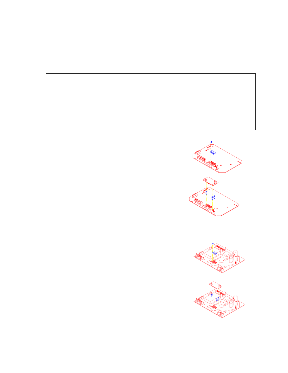
To install the RS-485 Network Option (350 die cast):
1. Open the indicator.
Remove the four screws from the back of the unit. It may help to
remove the swivel bracket, if installed.
Remove the rear cover.
2. Remove the U6 IC from its socket.
3. Remove the white wire jumper.
4. Snap the plastic spacers into the three mounting holes.
5. Gently press the option board into the socket.
6. Reinstall the back cover. Tighten the screws to at least 8 in/lb
torque.
7. Place the included sticker over the rear connector sticker RS232.
To install the RS-485 Network Options (350 Stainless and 355):
1. Open the indicator.
Remove the eight screws from the back of the unit and remove the
cover.
2. Apply the included sticker to the J6 comm port. The label will go
over the silk screen on the board.
3. Remove the U6 IC from its socket.
4. Remove the white wire jumper.
5. Snap the plastic spacers into the three mounting holes.
6. Gently press the option board into the socket.
7. Reinstall the back cover. Tighten the eight screws securely to create
a good seal.
Figure 24: RS-485 Installation (Die
Cast 350)
Figure 25: RS-485
Installation (Stainless
350/355)