Holtgreven GSE-355 I.S. User Manual
Page 29
20
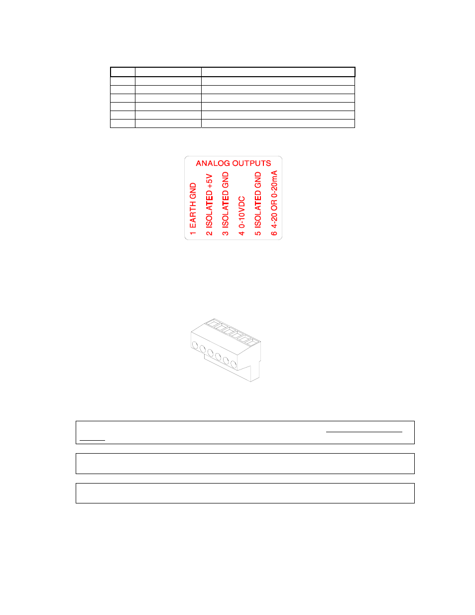
Table 2: Analog Output Connections
Pin Connection
Name Description
1 Earth
Ground
Non-isolated earth ground (future use).
2
+ 5 VDC
Isolated 5 volt source (future use).
3
Isolated Ground
Provides an isolated ground connection.
4
Vout
Used for the 0-10 VDC analog signal output.
5
Isolated Ground
Provides an isolated ground connection.
6
Iout
Used for 4-20 or 0-20 mA analog signal output.
Place this label on the rear of the indicator (die cast), above the analog option knockout.
(Stainless steel model) Cut off the text “ANALOG OUTPUTS” from the label and place it on the connector shown
below (apply to the area just under the field external wire terminals).
Wire the option connector in accordance with the label (left to right).
A
NALOG
B
OARD
D
IAGNOSTIC AND
T
EST
P
ROCEDURES
The following test procedures affect the analog output signal levels. Be sure to disconnect all peripheral
devices attached to the analog option card.
Test equipment needed: precision DC voltmeter, 500 ohm precision resistor. The 500 ohm resistor must
meet the following specifications: .01% tolerance and 5ppm temperature coefficient.
This test procedure requires that the initial analog option calibration procedure has been completed