Setpoint card connections – Holtgreven GSE-355 I.S. User Manual
Page 35
26
Setpoint Card Connections
Using one of the software setpoint configurations (see General Setpoint Setup on page 63) in conjunction with the
setpoint option board gives the Model 350/355 the ability to directly control external devices such as valves, relays,
actuators, etc.
There are up to three setpoint outputs available. The activation and deactivation is controlled by the setpoint
configuration. The outputs are capable of driving up to one Amp at 20-280VAC & 2 Amp at 3-60VDC. The solid state
relays are normally open (NO) contacts.
See General Setpoint Setup on page 63 for setpoint software configuration details.
The Model 350/355 contains components which could be damaged by Electrostatic Discharge (ESD) if
serviced improperly. Use proper ESD precautions (wear a wrist strap connected to ground, use grounded
work stations, etc.) when opening the enclosure.
High voltages may exist within the enclosure! To prevent the risk of electrical shock, ALWAYS unplug the
Model 350/355 when opening the enclosure. Installation and servicing of the Model 350/355 should be
performed by authorized and qualified service personnel only.
Never connect or disconnect option board cables while the indicator is powered. Doing so may result in
circuit board damage.
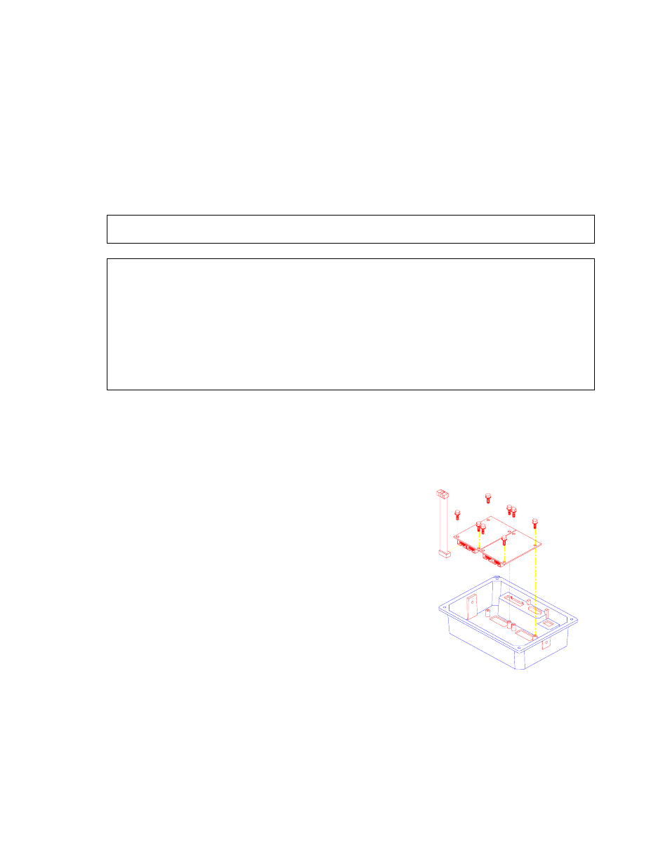
To install the Setpoint Control Module (350 die cast):
1. Open the indicator.
Remove the four screws from the back of the unit. It may help to remove the swivel bracket, if installed.
2. Place the back of the indicator, open side down, on a firm surface. Using a hammer and screwdriver,
remove the appropriate knock-out.
It helps to place the screwdriver tip on the knockout pad, rather
than in the groove. The knock-outs do not require much force to
remove. If only installing one option, the left knock-out (as viewed
from the rear) should be removed. A small file may be used to
remove any burrs.
3. Flip the back cover over and place the Setpoint Control Module,
component side down, over the four mounting holes. Install four
10mm screws to a minimum of 8 in/lb of torque.
Be sure the cable is already attached before installing the card.
Also be sure the cable is attached to the left-most connector (as
viewed from the component side of the option board). The second
connector is for ‘daisy-chaining’ another option card. The screws
used to mount the option card are self-tapping and will require
added torque when first installed.
4. Attach the loose end of the cable to the serial I/O connector (J7) on
the main board or the open connector of a previously installed
option card.
J7 is a 10-pin polarized connector. Be sure the cable is not twisted when installed. If this is a second
option card, route the cable to the open connector of the first option card.
5. Reinstall the back cover. Tighten the four screws to a minimum of 8 in/lb torque.
Figure 21: Option Board
Installation (Die Cast Model 350)