Holtgreven GSE-355 I.S. User Manual
Page 26
17
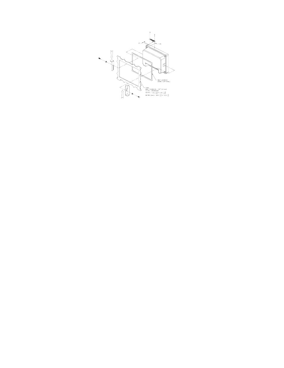
Figure 18: Model 350 Panel Mount Installation (Die Cast Model)
o
INDICATOR CAN BE INSTALLED USING EITHER BUTTON OR HEX HEAD SCREWS. BOTH TYPES OF SCREWS ARE
SUPPLIED WITH THE KIT.
o
APPLY PRESSURE ON MOUNTING BRACKETS IN DIRECTIONS SHOWN. THIS WILL ENSURE THE INDICATOR IS DRAWN
FIRMLY AGAINST THE PANEL.
o
DRILL 1/16 (.0625) DIA. PILOT HOLES FOR PINS.
o
ADD INDICATOR'S SERIAL NUMBER TO THE LABEL.
To install the Model 350 Panel Mount Kit:
1. Unpack the Panel Mount Kit.
Be sure that all parts shown in Figure 18 are accounted for.
2. Remove the two plastic Heyco plugs.
The plugs are located in the threaded bracket mounting holes on either side of the indicator. Be careful not
to scratch the finish of the indicator when removing these plugs.
3. Place the adhesive gasket around the panel cutout.
This step is optional. The gasket should be adhered onto the outside of the panel and centered around the
cutout.
4. Place the Model 350 through the panel cutout.
This step may require a second person to hold the indicator in place. The indicator should be centered
inside the cutout.
5. Using two small screws and star washers, attach the two panel mount brackets. The center holes of the
brackets should align with the threaded bracket mounting holes on either side of the indicator. The two
brackets should angle away from the indicator.
6. Using four long screws and four lock-nuts, secure the indicator to the panel. Thread the lock-nuts onto the
screws so that they will not interfere with tightening the screws into the threaded bracket holes. Evenly
tighten the four screws until they are snug. Do not over-tighten. Now thread the lock-nuts down until they
are snug against the bracket.