System bus (can / can−aux) configuration – Lenze ECSCAxxx User Manual
Page 167
System bus (CAN / CAN−AUX) configuration
Axis synchronisation (CAN synchronisation)
l
167
EDBCSXA064 EN 3.2
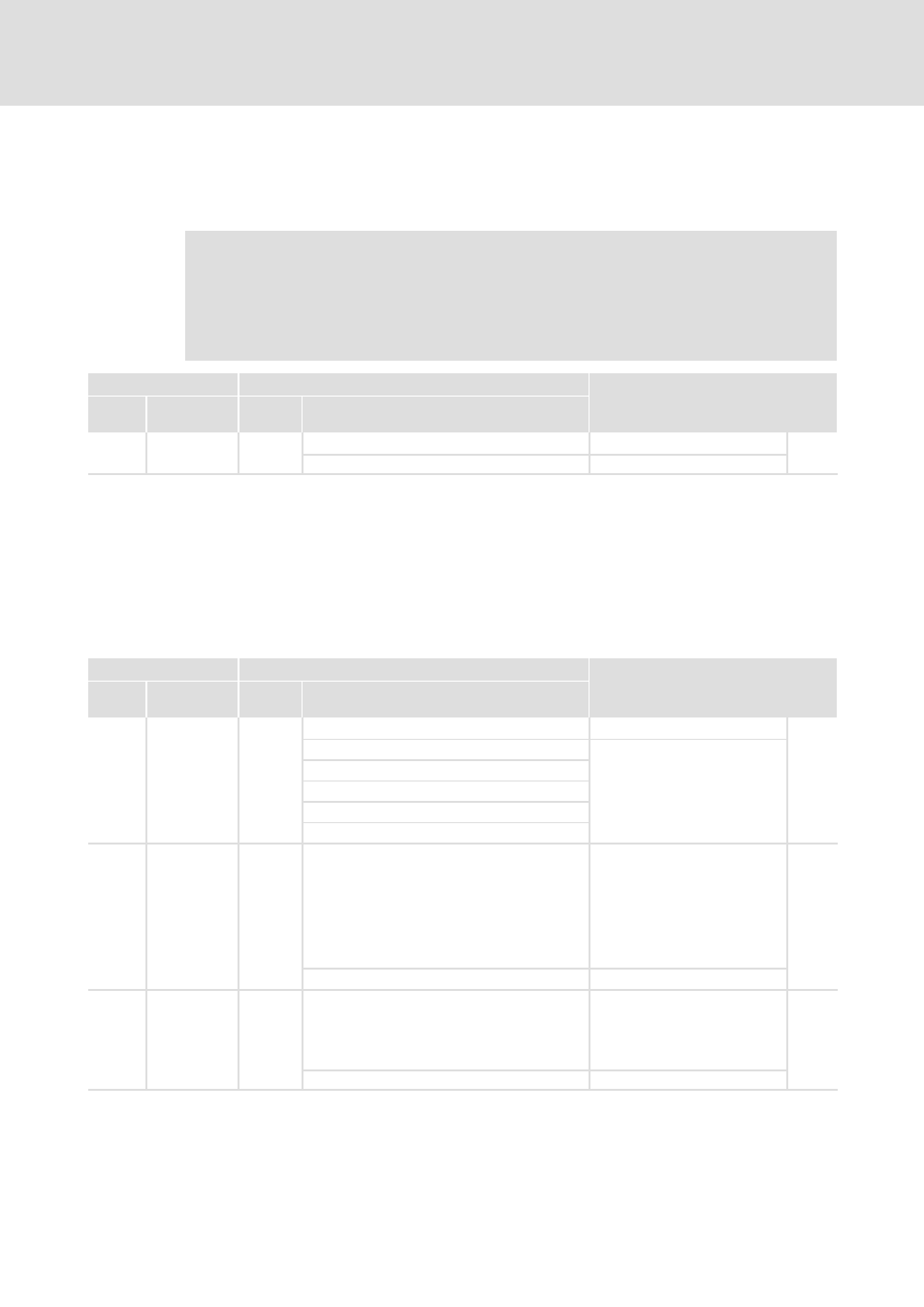
Phase shift
The synchronisation phase (C1122) defines the period of time of the offset by which the
start of the controller−internal cycle lags behind the sync signal received.
)
Note!
Always set the synchronisation phase higher than the maximum possible
"jitter" of the received CAN sync telegrams!
phase shifting and thus periodic changes of signal frequencies are called
"Jitter".
Code
Possible settings
IMPORTANT
No.
Designation
Lenze/
{Appl.}
Selection
C1122 Sync phase
0.460
Synchronisation phase
^ 167
0.000
{0.001 ms}
6.500
Start of axis synchronisation
After mains connection and the initialisation phase, the synchronisation is started. After
the first sync telegrams have been received, it takes a few seconds until the system is
compensated. The duration of this process is basically determined by the interval of the
sync signals and the sync correction increment.
The CAN sync correction increment (C0363) indicates the increment used to extend or
shorten the control cycle (e.g. to shift the start time).
Code
Possible settings
IMPORTANT
No.
Designation
Lenze/
{Appl.}
Selection
C0363 Sync correct.
1
CAN sync correction increment
^ 167
1
0.2
ms/ms
2
0.4
ms/ms
3
0.6
ms/ms
4
0.8
ms/ms
5
1.0
ms/ms
C0369 SyNc Tx time
0
CAN sync transmission cycle for
CAN bus interface X4
A sync telegram with the
identifier of C0368 is sent with
the cycle time set.
ECSxP: The setting is effected
automatically depending on
C4062!
^ 167
0
{1 ms}
65000 0 = switched off
C2469 Sync Tx time
0
CAN−AUX sync transmission cycle
for CAN bus interface X14
A sync telegram with the
identifier of C2468 is sent with
the set cycle time.
^ 166
^ 163
0
{1 ms}
65000 0 = switched off