Front view, 9 hardware operation - edge switch hardware view – HP StorageWorks 2.32 Edge Switch User Manual
Page 48
Monitoring and managing the switch
48
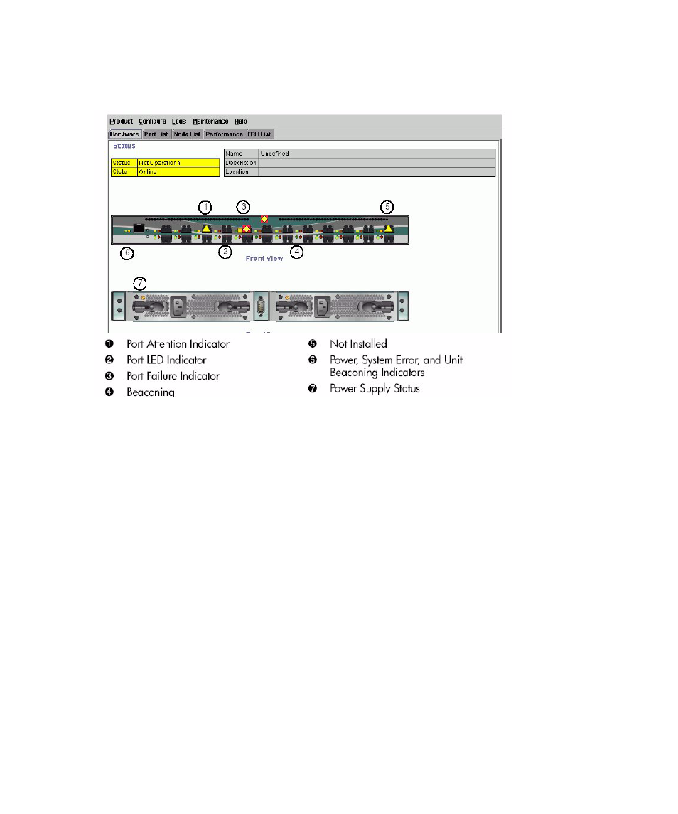
illustrates the Hardware View for the Edge Switch. The figure includes examples of
symbols and LED indicators that display to help you monitor hardware operation. The numbers
called out in
are keyed to descriptions in the sections, ”
Figure 9
Hardware operation - Edge Switch Hardware View
Front view
1.
Port attention indicator
The yellow triangle on the port connector graphic indicates that a link incident occurred or that
the port is not operational, in nonstandard mode of operation, or has other status. You can
determine the reason for a link incident by displaying the Port Properties dialog box for the
port. For details on status symbols, see
on page 72. For information on link incidents,
see ”
2.
Port LED indicator
The two round indicators (green or blue and amber) to the left of each port connector simulate
LED operation on the actual switch port. A green LED indicates that the port is online with an
operating speed of 1 gigabit per second (Gbps). A blue LED indicates that the port is online
with an operating speed of 2 Gbps. When the amber indicator illuminates steadily, the port
has failed and requires service. For details on port LED indicator operation, see
on
3.
Port failure indicator
A blinking red and yellow diamond over a port connector indicates that the port has failed. See
on page 72 for details on port operating states and the status symbol and indicator
operation.