Index, Alarm setting – Yokogawa DAQWORX User Manual
Page 21
1-13
IM WX102-01E
1
2
3
4
5
6
7
8
9
10
11
Index
Before Operation
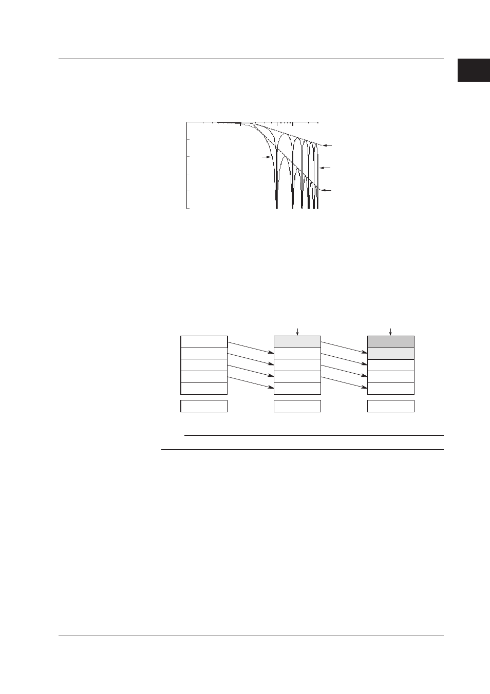
Input filter
The filter can be turned ON and OFF to reduce normal mode noise. Effects on normal
mode noise are shown below (theoretical values).
0dB
-20dB
-40dB
-60dB
-80dB
-100dB
1Hz
10Hz
100Hz
50Hz
300Hz
Slope; -20dB/dec
Slope; -60dB/dec
Filter OFF
Filter ON
Frequency
Attenuation
Moving average
A moving average value for the 2 to 64 latest measured values can be calculated. Use
of the moving average function suppresses fluctuation of input signals, thus resulting in
smooth waveforms.
For the first sampling following designation of the moving average function, the specified
number of data sets are not acquired, thus all the data are considered to be the first
sampled data for moving average.
10.0mV
5.0mV
0.0mV
–5.0mV
–10.0mV
0.0mV
Moving
average
15.0mV
10.0mV
5.0mV
0.0mV
–5.0mV
5.0mV
10.0mV
15.0mV
10.0mV
5.0mV
0.0mV
8.0mV
New data
Buffer data obtained
at "n + 1"th sampling
New data
Buffer data obtained
at nth sampling
Buffer data obtained
at "n + 2"th sampling
Deleted
Deleted
Note
Setting moving average on the pulse input channel doesn’t effect the measured value.
Alarm setting
The following six types of alarm are provided for each channel.
Up to four alarm values (levels) can be designated for each channel. For DI input, alarm
values are set to “1” (ON) or “0” (OFF). If an alarm value is designated, an alarm signal
will be output from the alarm output relay when the measured value reaches this alarm
value.
• H: Upper limit alarm
Triggers an alarm when the measured value exceeds the designated alarm value.
• L: Lower limit alarm
Triggers an alarm when the measured value drops below the designated alarm value.
• RH: Rate-of-change upper limit alarm
Triggers an alarm when positive change of measured value exceeds the specified
value within the specified interval.
1.5 DA100 Functions