Index, Explanation – Yokogawa DAQWORX User Manual
Page 178
8-5
IM WX102-01E
1
2
3
4
5
6
7
8
9
10
11
Index
Calibration
Explanation
Perform the calibration in the following sequence:
Universal Input Module
20mV ZERO > 20mV SPAN > 60mV ZERO > 60mV SPAN > 200mV ZERO
> 200mV SPAN > 2V ZERO > 2V SPAN > 6V ZERO > 6V SPAN
> 20V ZERO > 20V SPAN > 50V ZERO > 50V SPAN > Pt:1mA ZERO
> Pt:1mA SPAN > Pt:2mA ZERO > Pt:2mA SPAN > Pt:1mA-H SPAN
> Pt:2mA-H SPAN > Cu:2mA ZERO > Cu:2mA SPAN
DCV/TC/DI Input Module
Same sequence as the Universal Input Module except for the RTD (resistance
temperature detector).
mA Input Module
20mA ZERO > 20mA SPAN
Strain Input Module
2k ZERO > 2k SPAN > 20k ZERO > 20k SPAN > 200k ZERO > 200k SPAN
Digital Module
60mV ZERO > 60mV SPAN > 6V ZERO > 6V SPAN
Adjustable range/Error conditions/Display
The adjustable range is from -32768 to 32767.
However, 16384, –16384, 16385, and –16383 are excluded.
Note
The adjustable range is as described above. However, if the following conditions are not met,
the module is considered erroneous.
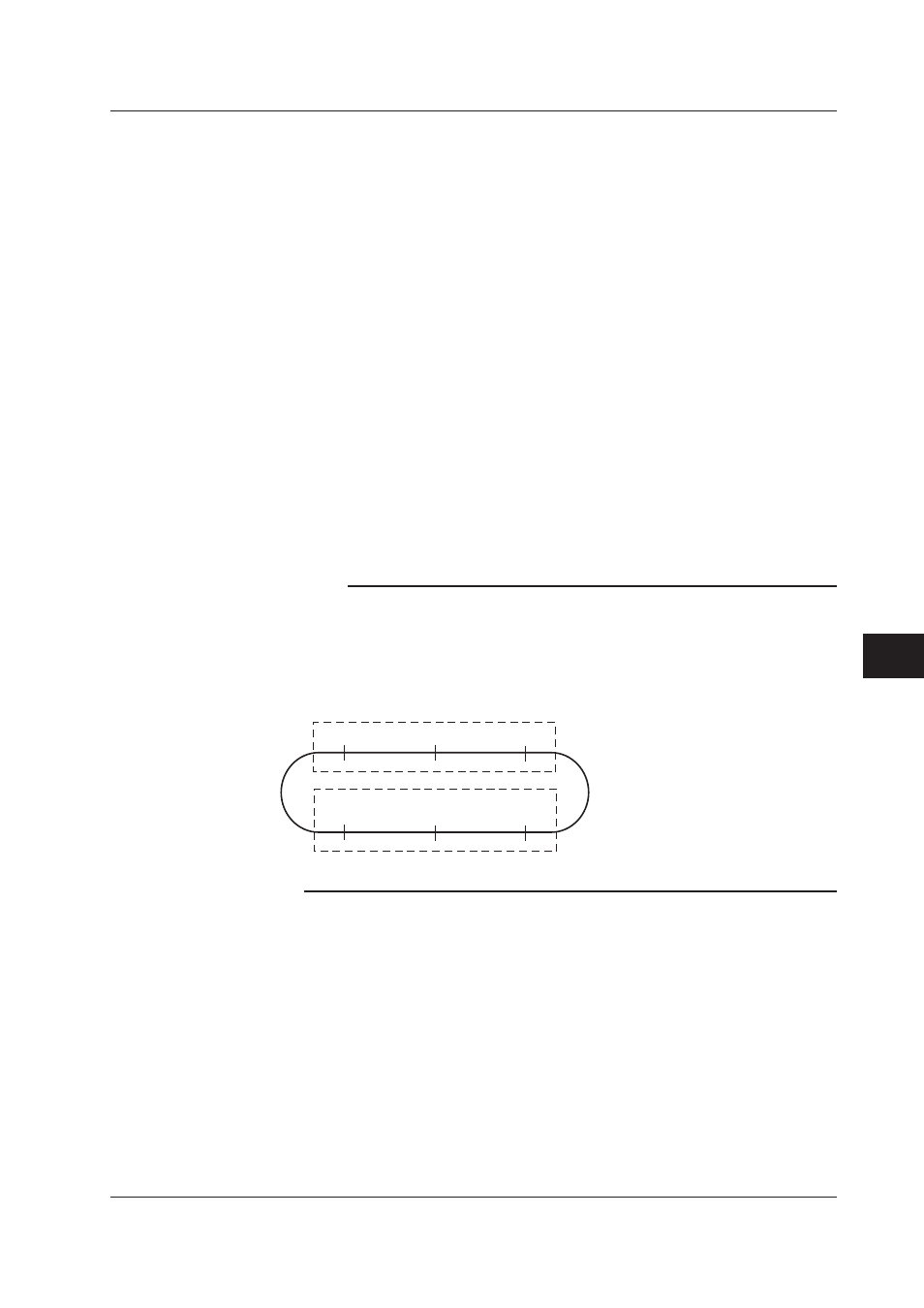
• ZERO calibration value: –3277 to 3277. The ideal value is 0.
• SPAN calibration value: 29491 to –29491. The ideal value is –32768.
19000 to 21000 for the strain input module. The ideal value is 20000.
(21000)
–29491
(19000)
29491
(20000)
–32768
ZERO calibration value
SPAN calibration value
–3277
0
3277
Values in parenthesis are for strain input modules.
8.3 Manual Calibration