Yokogawa DAQWORX User Manual
Page 142
6-6
IM WX102-01E
8
Set the waveform display area (Zone).
Note
• If the highest and lowest scale values are the same, then the highest setting will
automatically be increased with 1, and the lowest setting value will be decreased with 1.
• The lowest setting range for the Zone is 0 to 99%, the highest is 1 to 100%.
• In the waveform monitor display area, the lowest value is 0%, the highest value is 100%.
A trip point sets the position of a horizontal line on a waveform display you can
use to highlight specific values. You can set two different trip points. Trip point 1 is
displayed in red, trip point 2 in blue.
9
Set Trip point 1 and Trip point 2 ON (blue) or OFF for each channel.
10
Enter the appropriate Trip point 1 and Trip point 2 value.
Note
• The trip points actually displayed in the waveform display area are the trip points for the
active waveform.
• The Trip value must be within the Scale value set for each channel.
• You can change the position of the horizontal ‘trip’ lines by dragging the trip point labels on
the right side of the waveform display area with the mouse.
• Display will be set ON, when you set a Trip point. Click the Trip checkbox if you don’t want
the Trip to be displayed.
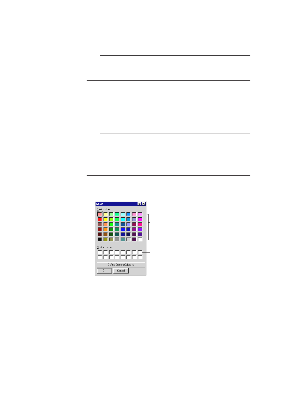
11
Click in the color channel of each channel to display the Color setting box. Select
the desired color and click OK.
Click the desired color
Click to create custom colors
Click to set desired custom colors
To make your own colors, click Define Custom Colors >>. The dialog box below
for setting custom colors appears. Set the desired hue, brilliance and brightness.
After setting the custom color, click Add to Custom Colors. Click OK to save the
colors.
12
To apply click OK (the General Display Settings dialog box will disappear), or
Apply, if you wish to keep the General Display Settings dialog box open.
6.3 General Display Settings