1 message frames (query and response), Modbus – IAI America ROBO Cylinder Series User Manual
Page 64
5. Modbus RTU
56
Modbus
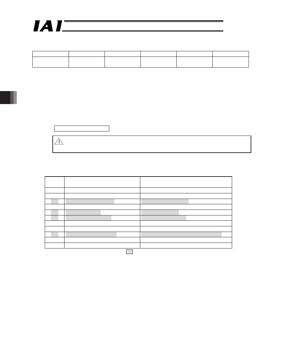
5.1 Message Frames (Query and Response)
Start
Address
Function code
Data
CRC Check
End
Silent
interval
1 byte
1 byte
n byte
2 byte
Silent
interval
(1) Start
This field contains a silent interval (non communication time) of 3.5 characters or longer.
(1 character = 10 bits)
Example: In case of 9600 bps, (10 x 3.5) bits x 1/9600 bps = 3.65 ms
Note If the response timeout error occurs, change parameter No. 45, “Silent interval
multiplier” or No. 17, “Min. delay for activating local transmitter” using the IAI teaching
tool as required.
(2) Address
This field specifies the addresses of connected RC controllers (01
H
to 10
H
).
Address = axis number + 1
Caution: The address is not equal to the corresponding axis number: be careful when
making settings.
(3) Function
The table below summarizes the function codes and functions that can be used with RC
controllers.
Code
[Hex]
Name
Function
01
H
Read Coil Status
Read coils/DOs.
02
H
Read Input Status
Read input statuses/DIs.
03
H
Read Holding Registers
Read holding registers.
04
H
Read Input Registers
Read input registers.
05
H
Force Single Coil
Write one coil/DO.
06
H
Preset Single Register
Write holding register.
07
H
Read Exception Status
Read exception statuses.
0F
H
Force Multiple Coils
Write multiple coils/DOs at once.
10
H
Preset Multiple Registers
Write multiple holding registers at once.
11
H
Report Slave ID
Query a slave’s ID.
17
H
Read / Write Registers
Read/write registers.
Note This manual explains about
mark function codes.
(Reference) The ROBONET gateway supports three types of function codes (03
H
, 06
H
and
10
H
).
[Please refer to the separate ROBONET Operation Manual.]