2 in case the host uses rs485 interface, Modbus, Specifications 21 – IAI America ROBO Cylinder Series User Manual
Page 29: 1) system configuration fig. 3.4
3. Specifications
21
Modbus
PCON-*
ACON-*
SCON-*
(RS485)
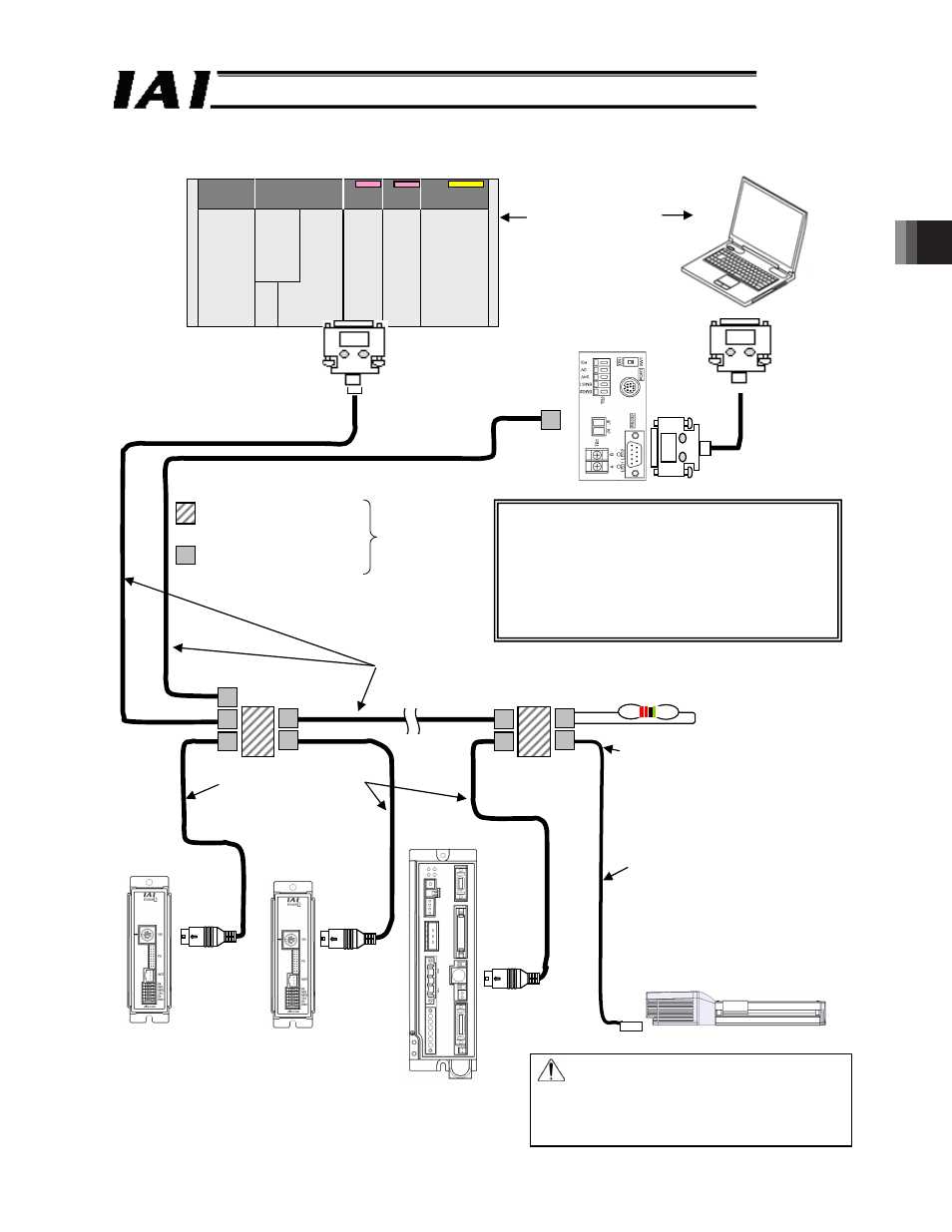
3.2 In Case the Host Uses RS485 Interface
(1) System configuration
Fig. 3.4
Master
/host
The host must be either a
PLC or PC. It is not
allowed to connect both at
the same time.
PC
SIO converter
Vertical specification: RCB-TU-
SIO-A
Horizontal specification: RCB-TU-
SIO-B
(RS232C RS485)
RS232C cross-connected cable
(prepared by the customer)
Junction
(5-1473574-4 made by AMP)
e-CON connector
(*-1473562-4 made by AMP)
Can be connected
using a terminal
block, instead.
Recommended cables
(Taiyo Cabletech HK-SB/20276xL (m) 2P x AWG22)
Prepared by the customer
Adjust to the master (host).
Controller link cables
CB-RCB-CTL002
(Comes with one junction,
one e-CON connector and
one terminating resistor with
R = 220 : 1/4 W)
Cable for network connection
CB-ERC2-CTL001
ERC3 power supply I/O cable
CB-ERC3P-PWBIO***
Note: The baud rate of an RC controller automatically
switches to 9600 [bps] if it detects a break (space) signal
lasting 150 [msec] or longer from the SIO port.
In some PCs, transmission lines are placed in break
condition when the communication port is not open. That if
such PCs are used, the baud rate of the connected RC
controllers may be set to 9600 [bps] unintentionally.
ERC3-SE
[Refer to Section 3.1 for connection of ERC2]
Caution Make sure to use the common 0 V line
of the 24 V power supply for each
controller (other than SCON).
For ROBONET connection, refer to the
separate ROBONET Operation
Manual.