Modbus – IAI America ROBO Cylinder Series User Manual
Page 31
3. Specifications
23
Modbus
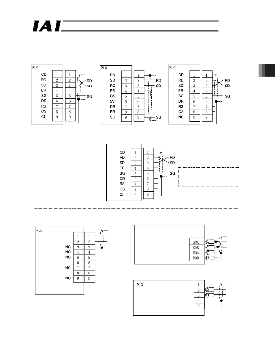
3.3 Communication Connector Pin Assignment of PLC and PC
(Reference)
Fig. 3.6
In case of PLC made by Mitsubishi:
QJ71C24 RS232C
D-sub 9-pin connector (male: cable side)
One end of the
shielded cable shall
be connected to a
connector housing
or grounded.
In case of PLC made by Omron:
CJ1W-SCB or SCU RS232C
D-sub 9-pin connector (male: cable side)
In case of PLC made by Keyence:
KV-L20R RS232C
D-sub 9-pin connector (female: cable side)
PC: RS232C
D-sub 9-pin connector (female: cable side)
PC
To use flow control, connect RS
and CS as well as DR and ER.
Connect the shielded cable
to the connector housing
In case of PLC made by Omron:
CJ1W-SCB or SCU RS485
D-sub 9-pin connector (male: cable side)
In case of PLC made by Mitsubishi:
QJ71C24 RS485
Terminal block
(Set the toggle switch
to a two-wire system)
Transmission data- (SDA)
Transmission data+ (SDB)
Reception data- (RDA)
Reception data+ (RDB)
Transmission data-
Transmission data+
One end of the
shielded cable shall
be connected to a
connector housing
or grounded.
Wire cables based on the printed signal
names on the communication unit panel.
Transmission data+
Transmission data-
Reception data+
Reception data-
Transmission data-
Transmission data+
One end of the
shielded cable shall
be connected to a
connector housing
or grounded.
Transmission data-
Transmission data+
One end of the
shielded cable shall
be connected to a
connector housing
or grounded.
In case of PLC made by Keyence:
KV-L20R RS485
Terminal block
1: SG
2: Reception data- (RDA)
3: Transmission data- (SDA)
4: Reception data+ (RDB)
5: Transmission data+ (SDB)
(Set the toggle switch on the 485 (2) side)
[* Please refer to operation manual of each manufacturer for detailed explanations.]
One end of the
shielded cable shall
be connected to a
connector housing
or grounded.