Modbus – IAI America ROBO Cylinder Series User Manual
Page 273
6. Modbus
ASCII
265
Modbus
(4) Query sample
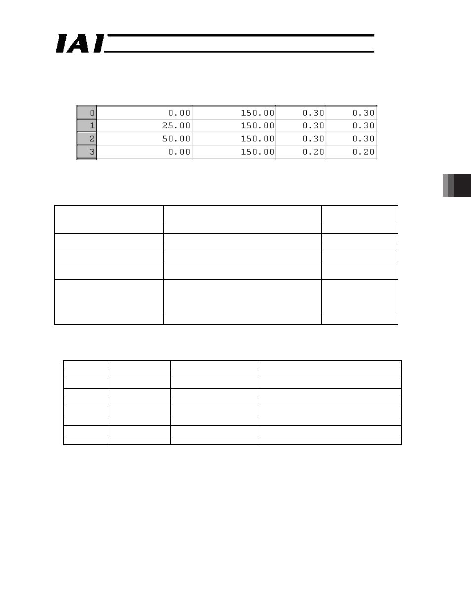
A sample query that moves a controller of axis No. 0 to start position 2 is shown below.
Sample start position setting
Fig.6.2
Query
First time
01 05 04 1D 00 00 D9 --- Write 0000
H
to set the edge
Second time 01 05 04 1D FF 00 DA --- Movement command
Field
ASCII mode 8-bit data
Converted ASCII
code data [H]
Start
‘:’
3A
Slave address [H]
‘0’, ‘1’
3031
Function code [H]
‘0’, ‘5’
3035
Start address [H]
‘0’, ‘4’, ‘1’, ‘D’
30343044
Changed data [H]
First time: ‘0’, ‘0’, ‘0’, ‘0’
Second time: ‘F’, ‘F’, ‘0’, ‘0’
30303030
46463030
Error check [H]
First time: ‘D’, ‘9’ (In accordance with LRC
calculation)
Second time: ‘D’, ‘A’ (In accordance with
LRC calculation)
4439
4441
End
‘CR’, ‘LF’
0D0A
If the change is successful, the response message will be the same as the query.
(5) Start address
Address
Symbol
Name
Function
0418
ST7
Start position 7
Move to position 7
0419
ST6
Start position 6
Move to position 6
041A
ST5
Start position 5
Move to position 5
041B
ST4
Start position 4
Move to position 4
041C
ST3
Start position 3
Move to position 3
041D
ST2
Start position 2
Move to position 2
041E
ST1
Start position 1
Move to position 1
041F
ST0
Start position 0
Move to position 0