4 communication, 1 message transmission timing, Modbus 4 communication – IAI America ROBO Cylinder Series User Manual
Page 36
4. Communicationn
28
Modbus
4 Communication
4.1 Message Transmission Timing
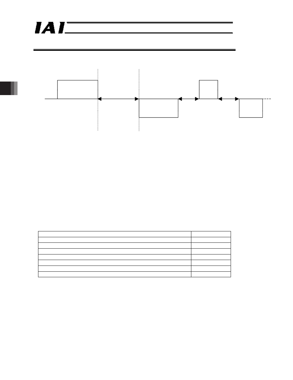
Fig. 4.1
The basic transmission control procedure consists of the master sending a query, and the RC
controller that received the query sending a response, which are considered one unit.
The delay time after a query message is received until a response message is sent is
calculated as the total sum of parameter No. 17 “Min. delay for activating local transmitter”
(default value 5 ms) and the internal processing time (refer to the table below).
After receiving a query message, the RC controller waits for the “min. delay for activating local
transmitter.” Once this delay time elapses, the controller will activate the transmitter and start
sending a response message. The master must enable the receive function of its own station
within the aforementioned delay time after sending a query message.
After sending a response message, the RC controller immediately prepares to receive the next
query.
Internal processing time
(Note 1)
Item
Time
Read/write a register other than those in the low-speed memory area 1 msec max.
Position data (1 position) Read
4 msec max.
Position data (1 position) Write
15 msec max.
Position data (1 position) Read/write
18 msec max.
Position data (9 positions) Read
9 msec max.
Position data (9 positions) Write
90 msec max.
Position data (9 positions) Read/write
98 msec max.
Note 1 Processing duration may differ depending on the category to access and the
controller type.ᴾ
ᴾ
Master (PLC, etc.)
Controller (slave)
Query
(message frame)
Delay time
= “Internal processing
time” +Min.
delay for activating
local transmitter”
(parameter No. 17)
Response
(message frame)
Delay time
Query
Delay time Response