Modbus – IAI America ROBO Cylinder Series User Manual
Page 38
4. Communicationn
30
Modbus
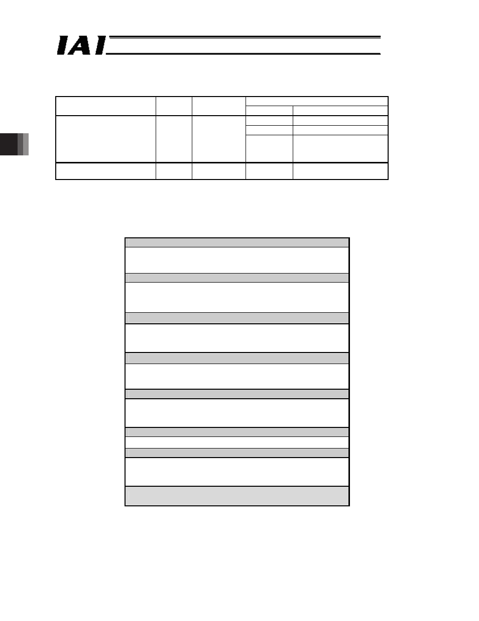
4.3 Internal Addresses and Data Structure of RC Controller
The memory area in your RC controller consists of the Modbus register area read/written in
units of words and the Modbus status are written in units of bits (coils).
Function
Memory area
Access
unit
Address
range
Code*
(Note)
Function
03
H
Read holding resisters
06
H
Write holding registers
Modbus register
[Refer to 4.3.1 and 4.3.2.]
Word
0500~9908
H
10
H
Write multiple holding
registers at the same
time
Modbus status
[Refer to 4.3.3 and 4.3.4.]
Bit
0100~043F
H
05
H
Write coils
(Note) Function codes explained in this manual
4.3.1 Structure of Modbus Registers
The layout of the Modbus registers is shown below.
Note Areas reserved for the system cannot be used for communication.
ᵎᵎᵎᵎ
ᵦ
ᴾ
(Reserved for system)
(Note)
ᴾ
ᵎᵓᵎᵎ
ᵦ
ᴾ
῍ᴾ
ᵎᵓᵎᵓ
ᵦ
ᴾ
Detailed information of the alarm detected latelyᴾ
ᴾ
(Reserved for system)
(Note)
ᴾ
ᵎᵢᵎᵎ
ᵦ
ᴾ
῍ᴾ
ᵎᵢᵎᵑ
ᵦ
ᴾ
I/O control information registersᴾ
ᴾ
(Reserved for system)
(Note)
ᴾ
ᵏᵎᵎᵎ
ᵦ
ᴾ
῍ᴾ
ᵑᵤᵤᵤ
ᵦ
ᴾ
Position table information
(low-speed memory area)ᴾ
ᴾ
(Reserved for system)
(Note)
ᴾ
ᵖᵒᵎᵎ
ᵦ
ᴾ
῍ᴾ
ᵖᵒᵐᵣ
ᵦ
ᴾ
Maintenance informationᴾ
*Applied models are PCON-CA/CFA, SCON-CA and ERC3.
ᴾ
(Reserved for system)
(Note)
ᴾ
ᵗᵎᵎᵎ
ᵦ
ᴾ
῍ᴾ
ᵗᵎᵏᵓ
ᵦ
ᴾ
Controller monitor information registersᴾ
ᴾ
(Reserved for system)
(Note)
ᴾ
ᵗᵖᵎᵎ
ᵦ
ᴾ
Position command registersᴾ
ᴾ
(Reserved for system)
(Note)
ᴾ
ᵗᵗᵎᵎ
ᵦ
ᴾ
῍ᴾ
ᵗᵗᵎᵖ
ᵦ
ᴾ
Numerical command registersᴾ
ᴾ
ᵤᵤᵤᵤ
ᵦ
ᴾ
(Reserved for system)
(Note)
ᴾ