Modbus – IAI America ROBO Cylinder Series User Manual
Page 188
6. Modbus
ASCII
180
Modbus
(4) Data
Use this field to add data specified by a function code. It is also allowed to omit data if data
addition is not specified by function codes.
(5) LRC Check
In the ASCII mode, an error check field conforming to the LRC method is automatically (*)
included in order to check the message content excluding the first colon and CR/LF. Moreover,
checking is carried out regardless of the parity check method of individual characters in
messages.
The LRC field consists of two ASCII code characters. The LRC value is calculated by the
sender that appends the LRC field to the message. The recipient recalculates the LRC value
while receiving the message, and compares the calculation result against the actual value
received in the LRC field. If the two values do not match, an error will generate.
* The host side must create a function that calculates the LRC value.
z
In case the message query is as follows: [‘:’] [“01] [“05”] [“040B”] [“0000”] [LRC] [CR] [LF]
[1] First, add all numerical values in units of bytes.
Total value added = 01
H
+ 05
H
+ 04
H
+ 0B
H
+ 00
H
+ 00
H
= 15
H
[2] Next, an 8-bit-based 2’s complement of this value is computed, yielding the value
FFFFFFEB
H
. The LRC value is obtained by extracting the least significant byte. Thus the
LRC value is “EB.”
(6) End
This is equivalent to the trailer, and use “CR/LF” in the ASCII mode. In ASCII code, 00
H
and 0A
H
are displayed.
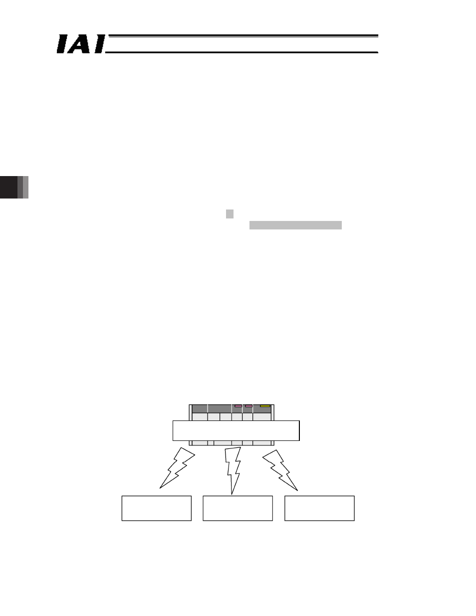
(7) Broadcast
It is possible to send a query containing same data to all connected axes by specifying the address
00
H
. In this case, no response is returned from the RC controllers.
Note, however, that the function codes etc. that can be used with this function are limited; care
should be taken when using the function. Please check the function codes that can be used in 6.3,
“List of ASCII Mode Queries.”
Fig.6.1
PLC (master)
Address = 00
H
(command all axes)
RC controller
(slave)
RC controller
(slave)
RC controller
(slave)