Modbus – IAI America ROBO Cylinder Series User Manual
Page 28
3. Specifications
20
Modbus
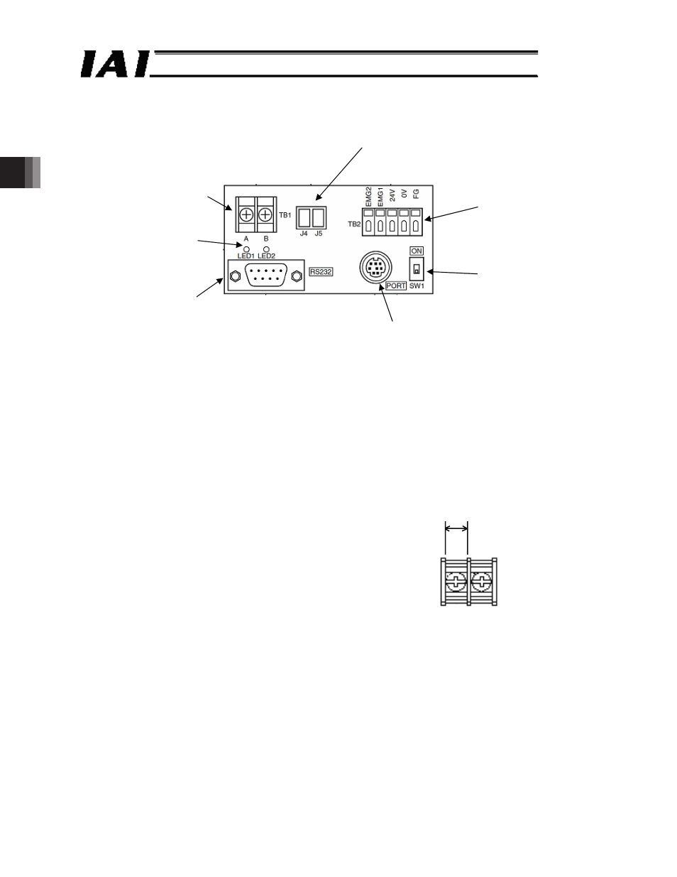
(3) SIO converter (vertical specification: RCB-TU-SIO-A, horizontal specification: RCB-TU-
SIO-B)
A RS232C RS485 converter
Fig. 3.3
~
Power supply and emergency stop terminal block (TB2)
x
EMG1 and EMG2: Discrete outputs of the emergency stop switch of the teaching
pendant
EMG1 and EMG2 are connected to the emergency stop switch of
the teaching pendant when the PORT switch is set to ON; EMG1
and EMG2 are short circuited when the switch is set to OFF.
x
24 V: Supply +24 V power (current consumption 0.1 A or less)
x
0 V: Supply 0 V power (use common 0 V for all 24 V DC-supplied controllers).
x
FG: A terminal to which FG is connected
* Compatible wires: Single wire: 0.8 to 1.2 mm
Twisted wire: AWG18 to 20 (strip length 10 mm)
~
Link connection terminal block (TB1)
A connector for link connection with an RC controller
x
A: Connect to pin 1 (SGA) of the communication
connector of the RC controller
x
B: Connect to pin 2 (SGB) of the communication
connector of the RC controller
~
D-sub 9 pin connector
A connector for connection with the master (host) side
~
Mini DIN8 pin connector
A connector for connection with teaching pendant or PC software
~
PORT switch
x
ON: A teaching tool is used.
x
OFF: A teaching tool is not used.
~
LED for monitoring (LED1 and LED2)
x
LED1: Turns on/flashes when the RC controller is transmitting
x
LED2: Turns on/flashes when the master (host) side is transmitting
~
Link connector (J4 and J5)
Connectors for link connection with an RC controller
An optional link cable (CB-RCB-CTL002) can be connected as is.
Link connection terminal block
(TB1)
LED for monitoring
(LED1 and LED2)
D-sub 9-pin connector
Link connector (J4 and J5)
Power supply and
emergency stop terminal block
(TB2)
PORT switch
Mini DIN8 pin connector
Terminal screw: M3Ч6
6.4