Modbus – IAI America ROBO Cylinder Series User Manual
Page 112
5. Modbus RTU
104
Modbus
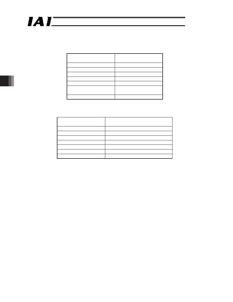
(4) Query sample
A sample query that reads the system timer value (from address 9010
H
) of a controller of axis No.
0 is shown below.
Query (silent intervals are inserted before and after the query)
01 03 90 10 00 02 E8 CE
Field
RTU mode
8-bit data
Start
Silent interval
Slave address [H]
01
Function code [H]
03
Start address [H]
9010
Number of registers [H] 0002
Error check [H]
E8CE (in accordance with
CRC calculation)
End
Silent interval
The response to the query is as follows.
Response (silent intervals are inserted before and after the response)
01 03 04 00 02 7A 72 F8 B6
Field
RTU mode
8-bit data
Start
Silent interval
Slave address [H]
01
Function code [H]
03
Number of data bytes [H] 04 (4 bytes = 2 registers)
Data 1 [H]
00 02 7A 72
Error check [H]
F8B6 (in accordance with CRC calculation)
End
Silent interval
The system timer is “00027A72” o Convert into decimal number o 162418 (ms)
The total time since the controller power was turned on is 162.418 sec.
Note The data of the response example is simply an example and will vary depending on
various conditions.