Modbus – IAI America ROBO Cylinder Series User Manual
Page 27
3. Specifications
19
Modbus
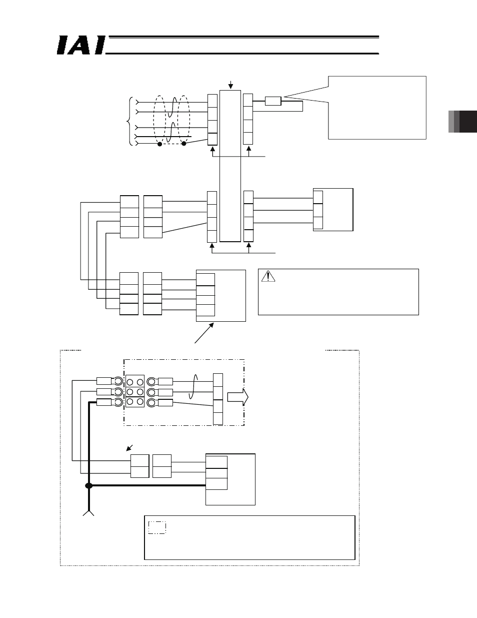
Fig. 3.2_2/2
1
2
3
4
1
2
3
4
1
2
3
4
1
2
7
SGA
SGB
GND
SGA
SGB
+5V
GND
1
2
3
4
1
2
3
4
1
2
3
4
1
2
3
4
1
2
3
4
ERC2-SE
SGA
SGB
GND
1
2
1A
1B
5B
1
2
1
2
3
4
1
2
3
4
2-pair shielded cables
Recommended cables:
Taiyo Cabletech
HK-SB/20276xL
2P x AWG22
(1) From the
previous page
4-directional junction
(5-1473574-4 made by AMP)
Terminating resistor R = 220 :
(comes with controller link cable)
When using a commercially
available RS232C RS485
converter, adjust the resistance
to the converter.
Cables for network connection
CB-ERC2-CTL001
Orange
Blue
Green
Controller link cable
CB-RCB-CTL002
Brown
Green
Blue
Orange
Orange
Blue
Brown
Green
Yellow
Orange
Blue
SIO-compatible power supply I/O cable
CB-ERC2-PWBIO***
e-CON connector (3-1473562-4 made by AMP)
Housing color: Green
Nth slave (N = maximum 16 slaves)
e-CON connector (3-1473562-4 made by AMP)
Housing color: Orange
In case of standard ERC2 products (the wiring processing is different from ERC2-SE)
J.S.T. Mfg V0.5-3 Terminal block
e-CON connector
Connected to junction
x
PIO-compatible power supply I/O cable
(CB-ERC-PWBIO***)
Red
Black
Orange (red 1)
Orange (black 1)
Pink (black 1)
ERC2-standard (PIO)
(Connect to the 0 V line
of the 24 V power
supply of ERC2)
Please prepare cables for the parts enclosed with dashed lines
and GND.
(Recommended cables: Taiyo Cabletech HK-SB/20276xL (m)
2P x AWG22)
Caution Make sure to use the common 0 V line
of the 24 V power supply for each
controller (other than SCON).
For ROBONET connection, refer to the
separate ROBONET Operation
Manual.
PCON/ACON/SCON