Modbus – IAI America ROBO Cylinder Series User Manual
Page 213
6. Modbus
ASCII
205
Modbus
6.4.9 I/O Port Input Signal Status Reading <
(1) Function
Port input values of the RC controller are read directly regardless of the PIO pattern. Note that the
values are the states of ports recognized by the RC controller as inputs.
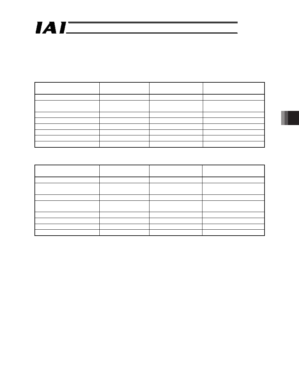
(2) Query format
Field
Number of characters ASCII mode character
string (fixed)
Remarks
Header
1
‘:’
Slave address [H]
2
Arbitrary
Axis number + 1
(01
H
to 10
H
)
Function code [H]
2
‘0’, ‘3’
Reading registers
Start address [H]
4
‘9’, ‘0’, ‘0’, ‘3’
Input port monitor register
Number of registers [H]
4
‘0’, ‘0’, ‘0’, ‘1’
Reading address 9003
H
Error check [H]
2
LRC calculation result
Trailer
2
‘CR’, ‘LF’
Total number of bytes
17
(3) Response format
A response message contains 16 bits of data per address.
Field
Number of characters ASCII mode character
string (fixed)
Remarks
Header
1
‘:’
Slave address [H]
2
Arbitrary
Axis number + 1
(01
H
to 10
H
)
Function code [H]
2
‘0’, ‘3’
Reading registers
Number of data bytes [H]
2
‘0’, ‘2’
Reading 1 register
= 2 bytes
Data 1 [H]
4
DI input value
DI input value [Hex]
Error check [H]
2
LRC calculation result
Trailer
2
‘CR’, ‘LF’
Total number of bytes
15