Modbus – IAI America ROBO Cylinder Series User Manual
Page 324
8. Reference Materials
316
Modbus
8.2 Configuration of Systems that Use both SIO and PIO
It is possible to monitor the current position and other values via the SIO (communication) by running the
RC controller with PIO. All queries that use function code 03 for either RTU and ASCII can be monitored.
Set PIO/Modbus switching (section 5.4.16 or 6.5.16) to the PIO side and, in case of RC controllers
equipped with a mode switch, set the switch to AUTO. The following RC controller models can use both
PIO and SIO.
x
PCON-C/CG/CF/CA/CAF, PCON-CY, PCON-PL/PO,
x
ACON-C/CG, ACON-CY, ACON-PL/PO,
x
SCON-C/CA,
x
ERC2
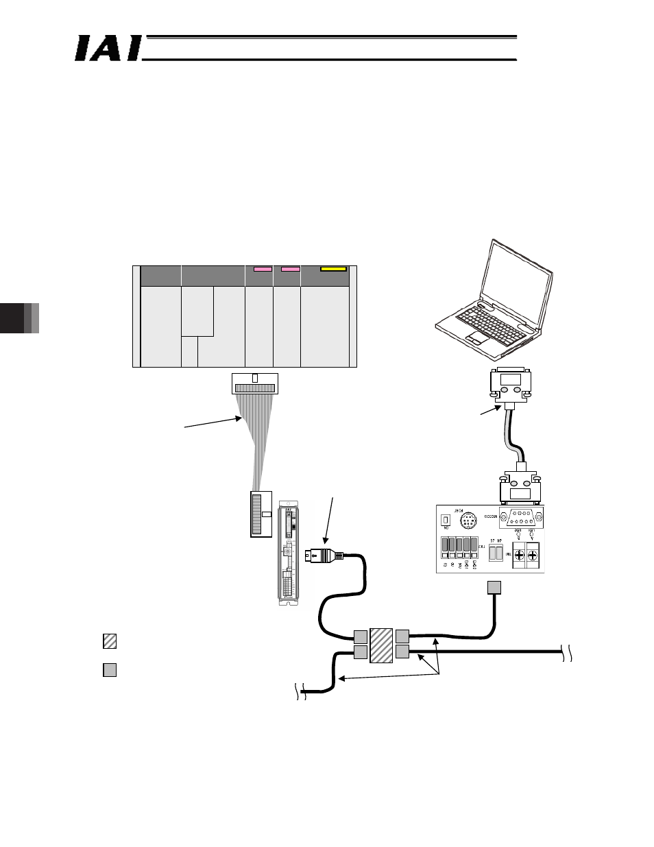
Example 1 of system configuration that uses both SIO and PIO
PLC
Fig. 11.1
x
PCON-C/CG/CA/CFA
Positioner I/O cable
(CB-PAC-PI0020)
2 m, comes with the controller
x
PCON-PL/PO
Pulse train I/O cable
(CB-PACPU-PI0020)
2 m, comes with the controller
PC
RS232C cross-connected cable
(prepared by the customer)
(Female)
Controller link cables
CB-RCB-CTL002
(Comes with one junction,
one e-CON connector and
one terminating resistor with
R = 220 : 1/4 W)
Master/
host
SIO converter
Vertical: RCC-TU-SIO-A
Horizontal: RCC-TU-SIO-B
(RS232C RS485)
Junction
(5-1473574-4 made by AMP)
e-CON connector
(*-1473562-4 made by AMP)
Recommended cables: Taiyo Cabletech
(HK-SB/20276xL (m) 2P x AWG22)
Prepared by the customer
PCON-C/CG
(RS232C)
PC